


Setup
XMV4280/XMV4140 Owner’s Manual
15
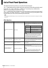
When using low impedance connections with
Double Power mode
If you use Double Power mode, input/output will be dis-
abled for channel B and channel D.
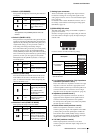
Depending on the impedance (4Ω or 8Ω) of the connected
speakers, set the [SPEAKERS] DIP switches as follows.
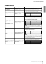
When using high impedance connections
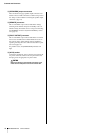
Depending on the specifications (70V or 100V) of the
system in which this unit is being installed, set the
[SPEAKERS] DIP switches as follows.
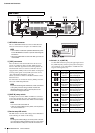
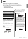
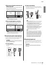
Connecting the speaker output connectors
The speaker output connectors on the rear panel are barrier
strip type connectors. We will explain connections using a
spade lug and connections using a bare conductor.
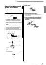
If using a spade lug
From below, insert the spade lug all the way, and tighten
the screw.
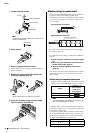
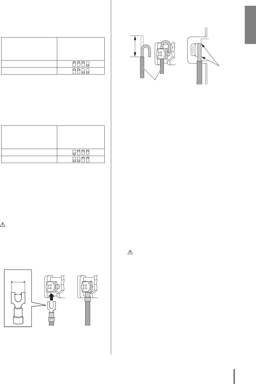
If using a bare conductor
Wrap the conductor around the barrier strip terminal as
shown below, and tighten the screw. Be sure that the bare
wire does not touch the chassis.
Connecting the power cord
Connect the included power cord to the [AC IN] connector
on the rear panel. First connect the AC power cord to the
socket on this unit, then plug it into an appropriate AC power
outlet.
Setting
Switches 1–4
(channel C)
Switches 5–8
(channel A)
560W{280W}, 8Ω
560W{280W}, 4Ω
NOTE
If you make settings for low impedance connections, the
HPF will automatically be turned OFF.
Setting
Switches 1–4
(channels C/D)
Switches 5–8
(channels A/B)
70V
100V
NOTE
If you make settings for high impedance connections,
the HPF will automatically be set to 80 Hz.
CAUTION
Make sure that the power is turned off. If the power is
on, you risk electrical shock.
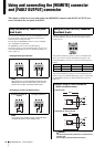
0.17"
(4.32mm)
<
0.33"
(
<
8.38mm)
=
=
NOTE
• If the [SPEAKERS] DIP switch 4 is in the lowered posi-
tion (Double Power mode), even if you do connect a
cable, audio will not be output from channel D.
• If the [SPEAKERS] DIP switch 8 is in the lowered posi-
tion (Double Power mode), even if you do connect a
cable, audio will not be output from channel B.
• Ensure that tension is not applied to the speaker cable.
• Connect the cables so that the amplifier’s “+” and “-”
symbols match those of the speaker. If they are
reversed, the phase will be inverted.
TIPS
Since a large amount of current can flow in a speaker
cable, a magnetic field will be generated. If sensitive cir-
cuits such as a microphone input cable or a microphone
amp are located near a speaker cable, electromagnetic
induction may produce noise in the input cable or circuit.
Input cables and devices that contain sensitive circuits
should be kept at a distance from speaker cables; we
also recommend that you fasten the cables in place.
CAUTION
You must turn off the power before connecting the
power cord.
15mm*
* Actual size Speaker cable
Wire should
not touch
the chassis.