


XMV4280/XMV4140 Owner’s Manual
13
Setup
This chapter explains how to set up the XMV to input analog signals.
If you are using the XMV along with the MTX, refer to the “MTX Setup Manual.”
Here we will make and verify the input/output settings as out-
lined below.
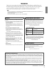
Rack-mounting the unit
Refer to “Precautions for Rack Mounting” (page 7), and
mount the XMV in your rack.
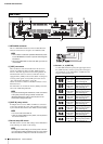
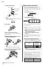
Checking the device setup DIP switch set-
tings
Make sure that all of the rear panel’s device setup DIP
switches are in the upward position.
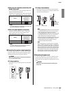
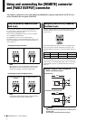
Connecting the analog inputs (Euroblock)
Connect the analog outputs of your mixer or other device to
the analog input connectors of the XMV.
You must use the supplied Euroblock plugs with tabs.
If these have been lost, please contact your Yamaha dealer.
NOTE
Refer to this manual for details regarding the following items, even if you are using the XMV along with the MTX.
• Making settings for speaker output
• Connecting the speaker output connectors
• Making high pass filter (HPF) settings
• Lowering the brightness of the indicators and the display
• Locking the panel
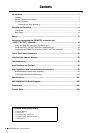
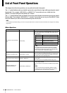
Explanation Page
Rack-mounting the unit 13
Checking the device setup DIP switch settings 13
Connecting the analog inputs (Euroblock) 13
Making settings for speaker output 14
Connecting the speaker output connectors 15
Connecting the power cord 15
Turning the power on 16
Enabling analog input 16
Making high pass filter (HPF) settings 16
Checking the wiring 17
Lowering the brightness of the indicators and the
display
17
Locking the panel 17
CAUTION
Steps earlier than “Turning the power on” must be per-
formed with the power off. If you perform these steps with
the power on, the settings might not be applied, or you
might be subject to electrical shock if you touch the con-
nectors.
12345678
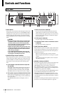
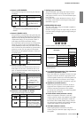
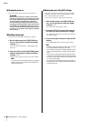
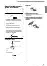
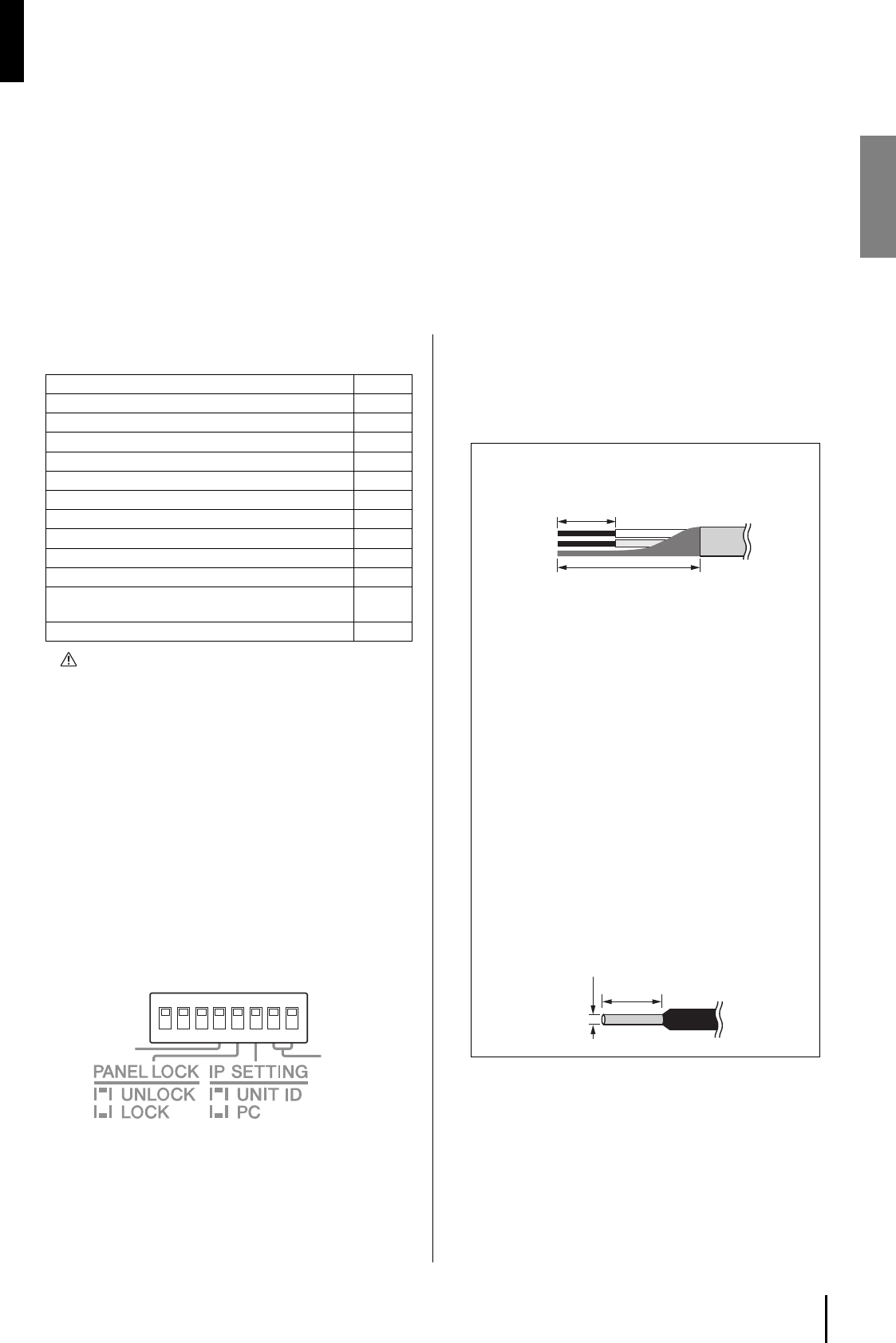
Cable preparation
• To prepare the cable for attachment to a Euroblock
connector, strip the wire as shown in the illustration
using stranded wire to make connections. With a
Euroblock connection, stranded wires may be prone
to breakage because of metal fatigue due to the
weight of the cable or due to vibration. Bundle the
cables and the Euroblock tabs using the supplied
cable ties (page 14). When rackmounting your
equipment, use a lacing bar when possible to bun-
dle and fasten the cables.
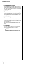
• If cables will be frequently connected and discon-
nected, as in the case of a portable installation, we
recommend that you use ferrules with insulation
sleeves. Use a ferrule whose conductor portion has
an external diameter of 1.6 mm or less, and a length
of approximately 7 mm (such as the AI0,5-6WH
made by the Phoenix Contact corporation).
approx.
7 mm
approx.20 mm
NOTE
Do not tin (plate with solder) the exposed end.
1.6 mm or less
approx.
7 mm