


6 T5n/T4n/T3n Owner’s Manual
Controls and Functions
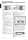
■ Front Panel
1 POWER switch and indicator
Press to toggle the power on or off. The POWER indicator
lights up green when the power is ON.
If the amplifier is connected to an amp control unit such as
the ACU16-C and the amplifier has been commanded to
enter STANDBY mode, this indicator will light orange.
2 TEMP indicator
Lights up red if the heat sink temperature exceeds 85°C
(185°F).
3 PROTECTION indicator
When the protection system is active, the indicator lights in
red. No sound will be output from the speakers, since the
speakers are automatically disconnected from the ampli-
fier’s outputs.
The protection system actives in the following situations:
•When the amplifier is turned on
The protection system actives for approximately 10
seconds when the amplifier is turned on. After 10 sec-
onds, the protection system deactivates automatically
and the amplifier is ready for normal operation.
• If the amplifier overheats
The protection system activates if the heat sink tem-
perature exceeds 85°C (185°F). The amplifier is
muted if the heat sink temperature exceeds 90°C (194
°F). The amplifier operates normally after the ampli-
fier cools down.
4 REMOTE indicator
This indicator will light green if the amplifier is being con-
trolled by an amp control unit such as ACU16-C.
5 CLIP indicator
Lights up red when the output signal distortion on the corre-
sponding channel rises above 1% — indicating that “clip-
ping” has occurred because the signal level is too high.
6 SIGNAL indicator
Lights up green when the corresponding channel’s output
level exceeds 1 Vrms (equivalent to 0.2 W into an 8 ohms
load, 0.4 W into a 4 ohms load or 0.8 W into a 2 ohms
load).
7 MUTE indicator
This indicator will light red if the amplifier is muted by an
amp control unit such as the ACU16-C. This indicator will
also light red while the PROTECTION indicator is ON.
8 Volume control knobs
Each control knob adjusts the volume of the corresponding
channel, in 31 steps from -∞ dB to 0 dB.
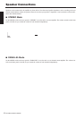
9 Air intakes
The amplifier uses forced-air cooling. The variable speed
cooling fan draws air in from the front and exhausts it
through the rear. The cooling fan speed varies depending
on the heat sink temperature: It operates at low speed when
it is below 40 °C (104 °F), increases in speed according to
increases in temperature, and operates at high speed when
temperature exceeds 60 °C (140 °F). Please be sure that
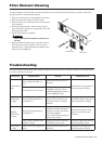
you do not block the air intakes or exhaust vents. Also,
clean the filter elements regularly. If the air intakes are
clogged with dust or debris, the amplifier will overheat,
which may result in the amplifier shutting down.
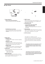
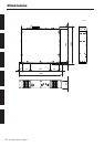
0 Screw holes for handles
These four screw holes are for the included handles. Fix
the handles to the amplifier, using the included flat-head
screws.
8130 074
2
56
99
6
T5n
Note: Screw holes for security cover
These four screw holes are for attaching a security
cover to protect the volume setting. Since a secu-
rity cover and screws are not included in the ampli-
fier, please prepare a security cover the same size
as indicated below and four M3 screws.
108 mm
30 mm
Front Rear
Air
exhaust
Air
intake