


English
E-9
Ⅵ Rear panel parts
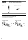
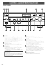
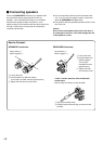
GND terminal (For turntable use)
Connecting the ground wire of the turntable to the GND
terminal will normally minimize hum, but in some cases
better results may be obtained with the ground wire
disconnected.
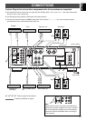
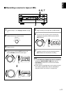
PRE OUT/MAIN IN terminals
Removing the jumper pins from the PRE OUT/MAIN IN
terminals enables this unit to operate separately as a
control amplifier and a power amplifier. These terminals are
used for connecting a signal-processing system such as a
graphic equalizer or a surround-sound processor to this
unit.
If such an external unit is connected to these terminals, the
VOLUME control of this unit can be used for adjusting the
overall sound level.
To connect an external unit, first remove the jumper pins
from the PRE OUT/MAIN IN terminals, and then connect
the input terminals of that unit to the PRE OUT terminals
and its output terminals to the MAIN IN terminals. For
details, refer to the owner’s manual included with the unit to
be connected.
Notes
● When you do not use the PRE OUT/MAIN IN terminals,
never remove the jumper pins from these terminals. If
removed, no sound will be outputted from this unit.
● When you use this unit with an external unit connected to
the PRE OUT and MAIN IN terminals, make sure that the
CD/DVD DIRECT AMP switch and the PURE DIRECT
switch on the front panel are turned off.
● When you use this unit as a power amplifier, connect the
output terminals of an external control amplifier etc. to
this unit’s MAIN IN terminals. In this case, this unit’s
controls will not function except the PHONES jack and
the SPEAKERS switches. Use the controls on the
external control amplifier to make volume adjustment etc.
*
1
*
2
*
3
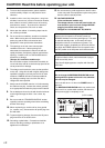
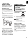
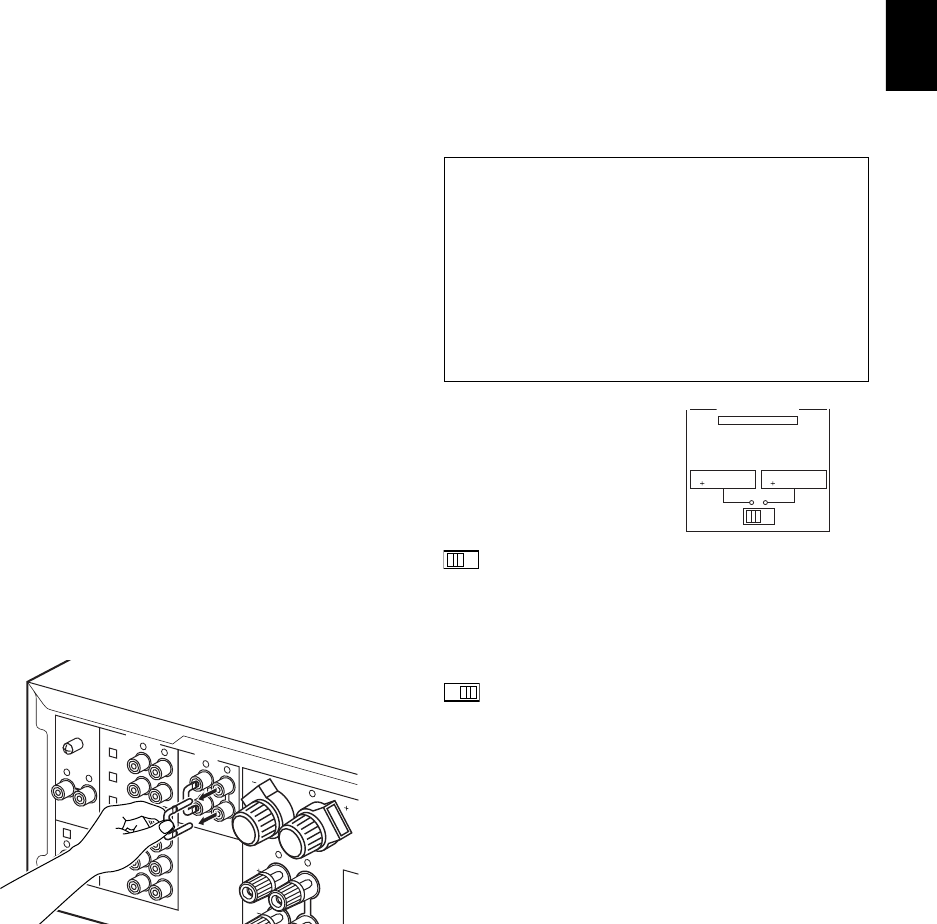
IMPEDANCE SELECTOR switch
WARNING
Do not change the IMPEDANCE SELECTOR switch
setting while the power to this unit is on, otherwise
this unit may be damaged.
If this unit fails to turn on when the POWER switch is
pressed:
The IMPEDANCE SELECTOR switch may not be set to
either end. If so, set the switch to either end when this
unit’s power supply is completely cut off.
Select the position whose
requirements your speaker
system meets.
(Left position)
If you use one pair of speakers, the impedance of
each speaker must be 4Ω or higher.
If you use two pairs of speakers, the impedance of
each speaker must be 8Ω or higher.
(Right position)
If you use one pair of speakers, the impedance of
each speaker must be 6Ω or higher.
If you use two pairs of speakers, the impedance of
each speaker must be 12Ω or higher.
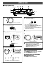
AC OUTLET(S) (SWITCHED)
(U.S.A., Canada, Europe, China and General models)
...................................................... 3 SWITCHED OUTLETS
(U.K. and Australia models)............. 1 SWITCHED OUTLET
Use these to connect the power cords of your components
to this unit.
The power to the SWITCHED outlets is controlled by this
unit’s POWER or STANDBY/ON switch. These outlets will
supply power to any connected unit whenever this unit is
turned on.
The maximum power (total power consumption of
components) that can be connected to the SWITCHED AC
OUTLET(S) is 100W.
IMPEDANCE SELECTOR
SET BEFORE POWER ON
A OR B : 6
Ω
MIN. /SPEAKER
A B : I2
Ω
MIN. /SPEAKER
A OR B : 4
Ω
MIN. /SPEAKER
A B : 8
Ω
MIN. /SPEAKER
GND
PHONO
2
TUNER
3
IN
(PLAY)
4
TAPE
OUT
(REC)
3
IN
(PLAY)
4
OUT
(REC)
MD
AUX
B
R
R
L
R
L
R
L
R
L
R
L
1
CD/DVD
PRE
OUT
MAIN
IN
AUDIO SIGNAL
COUPLER
*
4