5
Speakers & Volume Controls
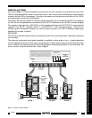
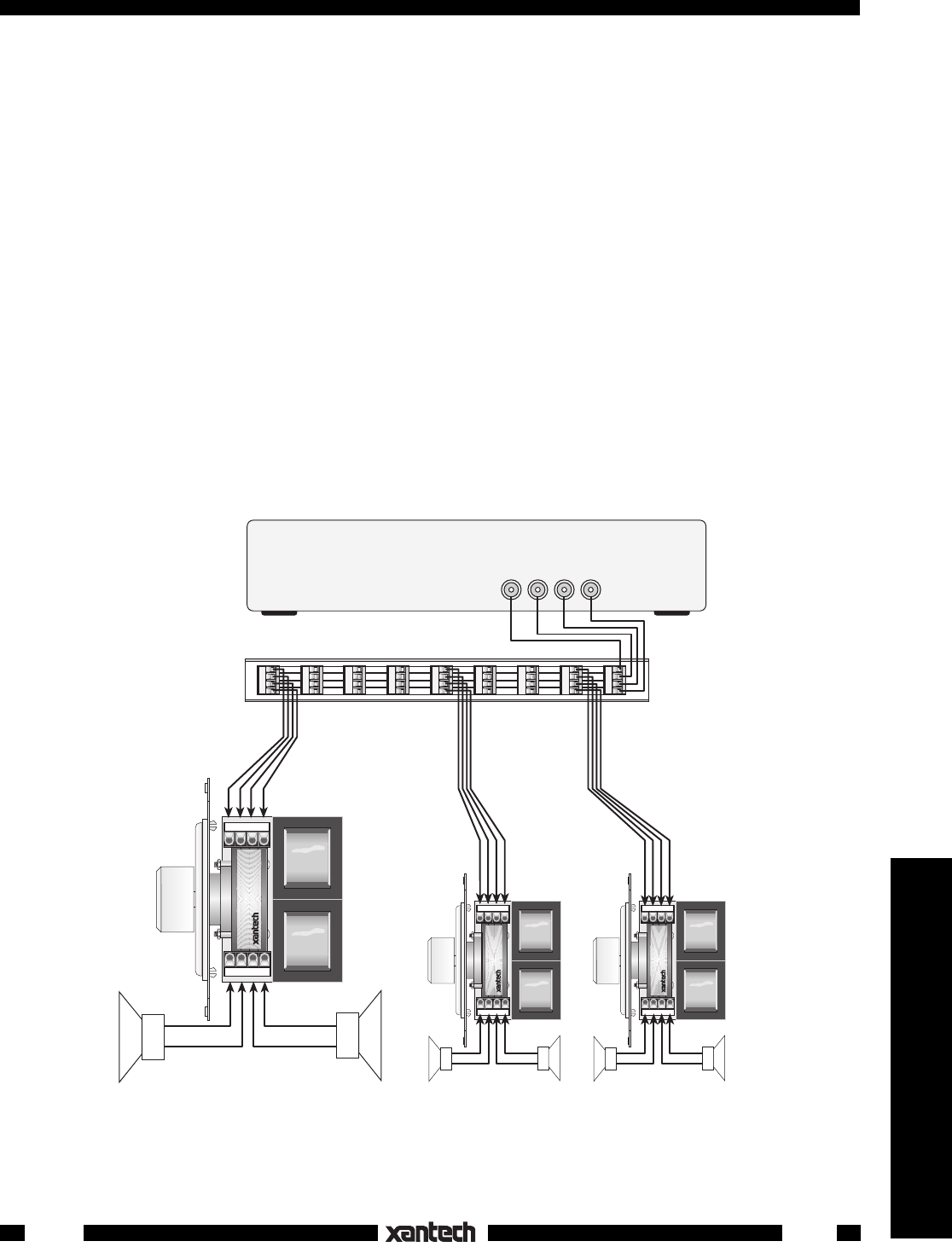
Fig. 3. A Typical 3-Room System
INSTALLATION
As shown in Fig. 3, 4-conductor speaker wire (two wires for each channel) is connected from each of the
760's to the power amplifier (home run from each room). Also, each channel (left and right) requires a pair
of wires from the 760 to the speakers. The plug-in connectors and the printed circuit board of the 760-00
are marked with the terminal identifications.
CAUTION:
Be sure the amplifier or receiver speaker terminals are connected to the INPUT terminals on
the 760-00 and the speakers are connected to the OUTPUT terminals on the 760-00 as shown in Fig.3!
The negative right input wire (INPUT R–) and the negative right output wire (OUTPUT R–) are connected
together in the 760-00. Likewise, INPUT L– and OUTPUT L– are connected together. There are no
common ground connections between the left and right channels in the 760-00, allowing bridged type
amplifiers to be used, if desired.
MOUNTING:
The 760-00 is intended to be housed in an electrical junction box and trimmed with a decorator-style plate
(not included).
The decorator-style plastic insert plate (supplied) is available in either white or ivory. 4 plastic tabs allow
it to be snapped into place onto the metal mounting plate. It can be easily removed for refinishing to other
colors, if desired, by squeezing the tips of the tabs together while pulling outward on the insert plate. Be
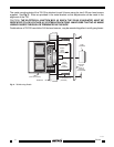
sure to remove the push-on knob first. Refer to Fig. 4.
760-00
L+ L- R- R+
L+ L- R- R+
L+ L- R- R+
L+ L- R- R+
L+ L- R- R+
L+ L- R- R+
L+ L- R- R+
L+ L- R- R+
L+ L- R- R+
1
2
34
56789
L+ L– R– R+
L+ L– R– R+
INPUT
OUTPUT
AMPLIFIER
OR
RECEIVER
RIGHT
SPEAKER
760-00
MATCH MAKER
Speaker
Volume
Controls
(side view
)
ROOM 1 ROOM 2 ROOM 3
–
+
LEFT
SPEAKER
–
+
RIGHT
SPEAKER
L+ L– R– R+
L+ L– R– R+
INPUT
OUTPUT
–
+
LEFT
SPEAKER
–
+
RIGHT
SPEAKER
L+ L– R– R+
L+ L– R– R+
INPUT
OUTPUT
–
+
LEFT
SPEAKER
–
+
SPEAKER
TERMINALS
CAUTION: Stereo receivers usually have two sets
of speaker terminals, "A" and "B". Be sure all speakers
connected to both "A" and "B" are taken into
consideration when paralleling speakers, so that the
amplifiers are not loaded by an impedance that is
lower than that specified by the manufacturer.
L+ L- R- R+
Use the CB18
to simplify multiple
speaker wire
connections.
760-00
SPEAKER VOLUME
CONTROL
SYLMAR, CA
®
760-00
SPEAKER VOLUME
CONTROL
SYLMAR, CA
®
760-00
SPEAKER VOLUME
CONTROL
SYLMAR, CA
®
CB18 "THE STRIP-IR" CONNECTING BLOCK


