


2
760-00
SETTING THE IMPEDANCE MATCHING JUMPERS
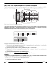
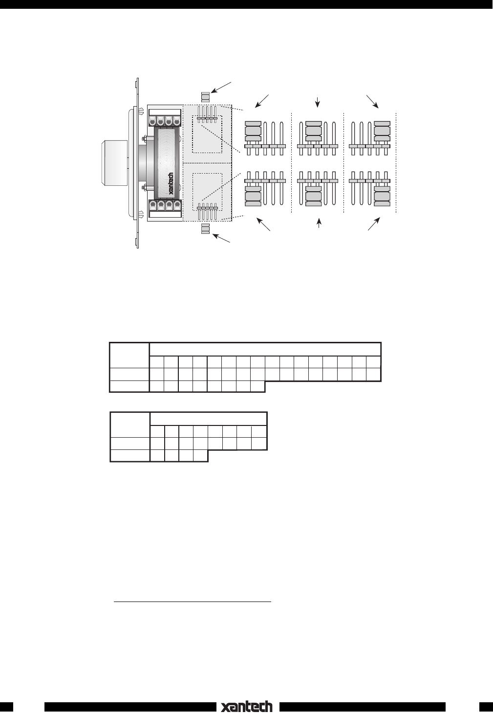
Fig. 2 shows the location of the pins and the jumper locations on the pins for the three impedance multiplier
positions. To set the jumpers correctly, refer to Fig. 2 and the charts and procedures that follow.
WHEN USING 8 OHM SPEAKERS
WHEN USING 4 OHM SPEAKERS
Number of Speaker Pairs Used
Min. Amp.
Impedance
S1 S4
1 2 3 4 5 6 7 8
S4 S4 S8 S8 S8 S8
S4 S4 S8 S8
4 Ohms
8 Ohms
Number of Speaker Pairs Used
S1 S1
1 2 3 4 5 6 7 8 9 10 11 12 13 14 15 16
S4 S4 S4 S4 S4 S4 S8 S8 S8 S8 S8 S8 S8 S8
S1 S4 S4 S4 S8 S8 S8 S8
Min. Amp.
Impedance
4 Ohms
8 Ohms
Fig. 2 Jumper Placement For Impedance Matching
The jumpers are located under the one side of the autoformers as shown in Fig.2. Their proper placement
depends on the number of 760's and speakers used in the total installation. To set them for the best
impedance matching condition, refer to the following charts and procedures:
Procedure for all 4 Ohm or all 8 Ohm Speakers:
1. Determine the rated speaker impedance (refer to the manufacturer's specifications - it must be the
same for all speakers used in the system).
2. Determine the total number of stereo speaker pairs used in the installation.
3. Determine the minimum safe amplifier operating load impedance (refer to the manufacturer's
specifications).
4. Find the correct jumper position from the above charts.
5. Place the jumpers
in the same position on each 760 used in the system.
Example 1:
Three pairs of 4 Ohm wall speakers are to be used with three 760's in a 3-room system, all driven by one
amplifier rated for 8 Ohms minimum safe operating load impedance.
1. Refer to the chart "WHEN USING 4OHM SPEAKERS".
2. Locate the number 3 in the top row.
Amplifiers & Preamplifiers
S8
S4S1
S8
S4S1
S8
S4
S1
S8
S4
S1
Right Channel Jumper
Left Channel Jumper
Left Channel Jumper Positions
Right Channel Jumper Positions
L+ L– R– R+
L+ L– R– R+
INPUT
OUTPUT
760-00
SPEAKER VOLUME
CONTROL
SYLMAR, CA
®