


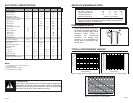
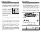
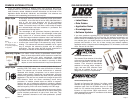
PAD LAYOUT
The following pad layout diagram is designed to facilitate both hand and
automated assembly.
PRODUCTION GUIDELINES
The modules are housed in a hybrid SMD package that supports hand or
automated assembly techniques. Since the modules contain discrete
components internally, the assembly procedures are critical to ensuring the
reliable function of the modules. The following procedures should be reviewed
with and practiced by all assembly personnel.
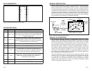
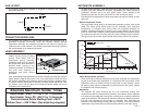
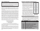
HAND ASSEMBLY
Pads located on the bottom of the
module are the primary mounting
surface. Since these pads are
inaccessible during mounting,
castellations that run up the side of
the module have been provided to
facilitate solder wicking to the
module’s underside. This allows for
very quick hand soldering for
prototyping and small volume
production.
If the recommended pad guidelines have been followed, the pads will protrude
slightly past the edge of the module. Use a fine soldering tip to heat the board
pad and the castellation, then introduce solder to the pad at the module’s edge.
The solder will wick underneath the module, providing reliable attachment. Tack
one module corner first and then work around the device, taking care not to
exceed the times listed below.
Absolute Maximum Solder Times
Hand-Solder Temp. TX +225°C for 10 Seconds
Hand-Solder Temp. RX +225°C for 10 Seconds
Recommended Solder Melting Point +180°C
Reflow Oven: +220°C Max. (See adjoining diagram)
Page 13Page 12
Castellations
PCB Pads
Soldering Iron
Tip
Solder
Figure 15: Soldering Technique
0.100"
0.070"
0.065"
0.610"
Figure 14: Recommended PCB Layout
AUTOMATED ASSEMBLY
For high-volume assembly, most users will want to auto-place the modules. The
modules have been designed to maintain compatibility with reflow processing
techniques; however, due to the their hybrid nature, certain aspects of the
assembly process are far more critical than for other component types.
Following are brief discussions of the three primary areas where caution must be
observed.
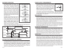
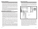
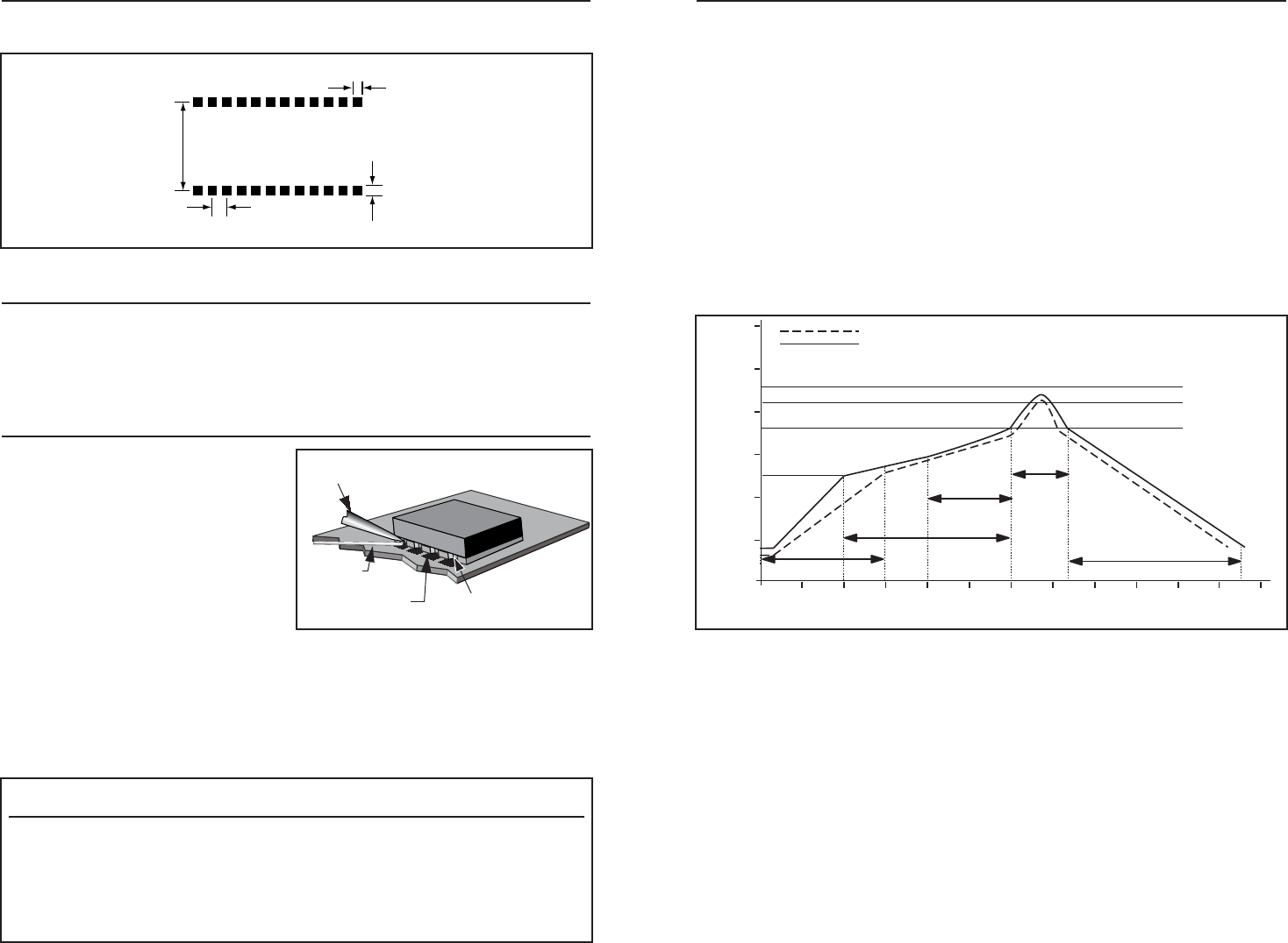
Reflow Temperature Profile
The single most critical stage in the automated assembly process is the reflow
stage. The reflow profile below should not be exceeded, since excessive
temperatures or transport times during reflow will irreparably damage the
modules. Assembly personnel will need to pay careful attention to the oven’s
profile to ensure that it meets the requirements necessary to successfully reflow
all components while still remaining within the limits mandated by the modules.
The figure below shows the recommended reflow oven profile for the modules.
Shock During Reflow Transport
Since some internal module components may reflow along with the components
placed on the board being assembled, it is imperative that the modules not be
subjected to shock or vibration during the time solder is liquid. Should a shock
be applied, some internal components could be lifted from their pads, causing
the module to not function properly.
Washability
The modules are wash resistant, but are not hermetically sealed. Linx
recommends wash-free manufacturing; however, the modules can be subjected
to a wash cycle provided that a drying time is allowed prior to applying electrical
power to the modules. The drying time should be sufficient to allow any moisture
that may have migrated into the module to evaporate, thus eliminating the
potential for shorting damage during power-up or testing. If the wash contains
contaminants, the performance may be adversely affected, even after drying.
125
o
C
600
0
50
100
150
200
250
300
120 180 240
30030 90 150 210 270 330 360
180
o
C
210
o
C
220
o
C
Temperature (
o
C)
Time (Seconds)
Ideal Curve
Limit Curve
Forced Air Reflow Profile
1-1.5 Minutes
2-2.3 Minutes
Ramp-up
Preheat Zone
Cooling
Soak Zone
Reflow Zone
20-40 Sec.
2 Minutes Max.
Figure 16: Maximum Reflow Profile