


Page 5Page 4
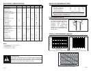
PIN ASSIGNMENTS
LADJ/GND
D0
D1 A9
A8
A7
A6
A5
A4
D2
GND
VCC
TE
D3
ANT
GND
1
2
3
4
5
6
7
817
18
19
20
21
22
23
24
D4
D5
D6 A1
A0D7
A3
A2
9
10
11
12 13
14
15
16
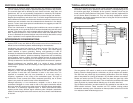
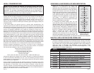
Figure 6: KH Series Transmitter Pinout (Top View)
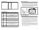
Pin # Name Description
1 GND / LADJ
Level Adjust. This line can be used to adjust the output
power level of the transmitter. Connecting to GND will give
the highest output, while placing a resistor to GND will
lower the output level.
2, 3,
7-12
D0 - D1
Data Input Lines. When TE goes high, the module will
encode the state of these lines for transmission. Upon
receipt of a valid transmission, the receiver / decoder will
replicate these lines on its output lines.
4 GND Analog Ground
5
V
CC
Supply Voltage
6 TE
Transmit Enable Line. When this line goes high, the
module will encode the states of the address and data lines
into a packet and transmit the packet three times.
13-22 A0-A9
Address Lines. The state of these lines must match the
state of the receiver’s address lines in order for a
transmission to be accepted.
23 GND Analog Ground
24 ANT 50-ohm RF Output
PIN DESCRIPTIONS
MODULE DESCRIPTION
The KH Series transmitter / encoder module combines a high-performance
Surface Acoustic Wave (SAW) based transmitter with an on-board encoder.
When combined with a Linx KH Series receiver / decoder, a highly reliable RF
link capable of transferring control or command data over line-of-sight distances
in excess of 300 feet is formed. The module accepts up to 8 parallel inputs, such
as switches or contact closures, and provides ten tri-state address lines for
security and creation of 59,049 (310) unique transmitter / receiver relationships.
The KH’s compact surface-mount package integrates easily into existing designs
and is friendly to hand production or automated assembly.
THEORY OF OPERATION
The KH Series transmitter operation is straightforward. When the Transmit
Enable (TE) line is taken high, the on-board encoder IC is activated. The encoder
detects the logic states of the data and address lines. These states are formatted
into a 3-word transmission, which continues until the TE line is taken low. The
encoder creates a serial data packet that is used to modulate the transmitter.
The transmitter section is based on a simple, but highly-optimized, architecture
that achieves a high fundamental output power with low harmonic content. This
ensures that most approval standards can be met without external filter
components. The KH Series transmitter is exceptionally stable over variations in
time, temperature, and physical shock as a result of the precision SAW device
that is incorporated as the frequency reference.
The transmitted signal may be received by any Linx KH Series receiver / decoder
module or Linx LC or LR Series receiver combined with the appropriate decoder
IC. Once data is received, it is decoded using a decoder IC or custom
microcontroller. The transmitted address bits are checked against the address
settings of the receiving device. If a match is confirmed, the decoder’s outputs
are set to replicate the transmitter’s inputs.
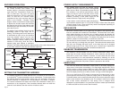
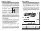
Output Isolation
& Filter
RF Amplifier
TRI-Detect
Buffer
Sync
GATE
Counter
Divider
TX Enable
Keyed Output
SAW
Oscillator
50Ω RF OUT
(ANT)
OSC
Parallel
Inputs
D0-D7
Address Inputs
A0-A9
RF STAGE ENCODER STAGE
Figure 7: KH Series Transmitter Block Diagram