


9
Installation
INSTALLING THE POWER SWITCH
1. Choose a location to install the MV-4000 power
ON/OFF switch. Remember when selecting a location
that you will need to run the +12VDC power cable
from the MV-4000 to the switch. Be sure the
switch is in the OFF position before continuing.
See Figure 9 page 10.
Wall or panel mount: Drill 1-1/4” hole, pull wires
through wall or panel.
Surface mount: Determine location and direction of
box. Mount box and feed wire into one of the box open
ings. Select plate cover (brown or white provided) and
snap the rocker switch into the switch plate. Be sure
switch is off!
2. Connect the ground wire from the vehicle and the
BLACK ground wire from the MV-4000 together,
using large yellow spade connector.
3. Connect the YELLOW spade connector to
the silver spade on the switch.
4. Connect the RED wire from the MV unit to the
small RED spade connector.
5. Connect small RED spade connector to center
spade on switch.
6. Connect the +12 V power wire from the vehicle to
a small RED spade connector.
7. Connect small RED spade connect to isolated
spade on switch.
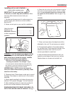
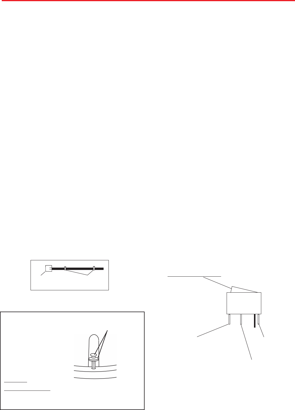
INSTALLING THE POWER SWITCH DIAGRAM
STEPS 2 & 3
TWO GROUND WIRES
1 FROM VEHICLE
1 BLACK WIRE FROM
SATELLITE DISH
STEPS 4 & 5
RED POWER
WIRE FROM
DISH
STEPS 6 &7
+12 V FROM VEHICLE
ON/OFF ROCKER SWITCH
WITH LIGHT
(Shown in OFF position.)
FIGURE 5
Terminals on switch have to be bent to fit in surface
mount box.
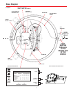
10. The GPS antenna is pre-wired and has a 1 meter
cable running through one of the connectors.
Determine location for GPS antenna. It is recom-
mended you place the GPS antenna 3 feet from
dome.
The recommended location for the GPS antenna is
based on having a level location and a clear view of
the sky for the best satellite signal acquisition. Do not
secure GPS antenna to roof at this time.
IMPORTANT! The GPS must be located minimum of
3 feet away from obstructions on roof of vehicle. An-
tenna must have a clear view of the sky for proper
operation.
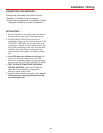
GPS installation —
CABLE-
ENTRY
CABLE
CLAMPS
FIGURE 4
1. Decide the best location for the cables to enter
the vehicle, and the location of the switch and re-
ceiver (see “Installing the switch and receiver”on
page 10). Drill a 1/2” hole in the roof, push wires in-
side. Make proper connections.
You must have filtered +12 VDC power source.
2. Place cable-entry plate over hole and cables.
Screw in place. Seal plate and screw holes with ap-
proved sealant (not included).
3. Depending on the length of the cable on the roof,
you may need to use cable clamps or wire ties (not
provided) between the unit and your cable-entry plate.
Clamping the cable every 12”-16” should eliminate
any unnecessary cable movement, Figure 6.
Cable entry installation —
INSTALLING THE DOME
Insert screw in holes on dome
rim. Be sure bolt is vertical;
not tilted to side. Place nut
under rim and tighten.
CAUTION:
DO NOT
OVERTIGHTEN!!
QUADREX
SCREW WITH
WASHER
(USE #2
PHILLIPS)