


SoundPlus
®
Infrared System • Model WIR SYS 90 PRO
SoundPlus
®
Infrared System • Model WIR SYS 90 PRO
D
D
NOTE: SPECIFICATIONS SUBJECT TO CHANGE WITHOUT NOTICE!
TX9 TX9
TX9 TX9
TX90
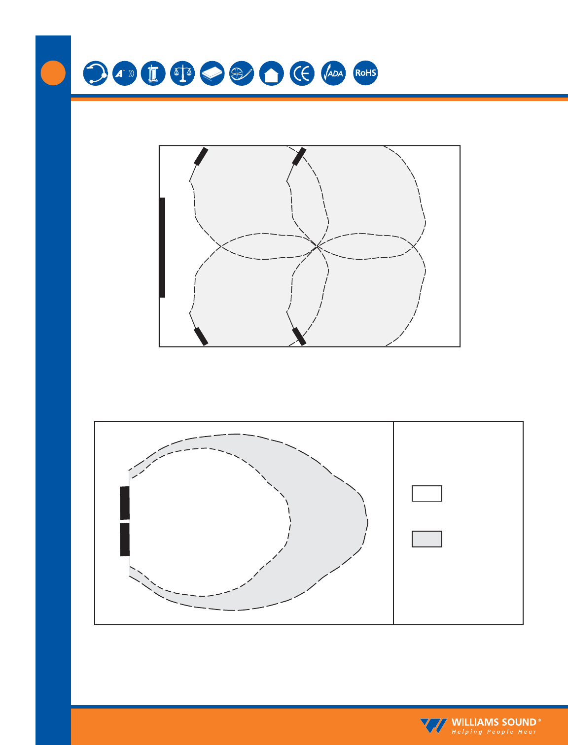
Coverage Area
with Single
Transmitter
Coverage Area
with Second Emitter
Added to Same
Emission Point
(50% increase)
TX9
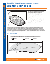
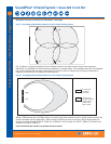
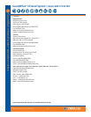
Fig. 7a: Overlapping Illumination Patterns to Cover Larger Listening Areas
Multiple Emitters Installed to Maximize Coverage
Fig. 7b: Overlapping Illumination Patterns to Cover Larger Listening Areas
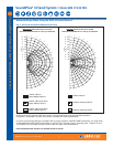
Fig. 7a above is a typical example of how multiple emitters are used to cover larger listening areas.
Generally it is desirable for the illumination patterns to overlap. Note: The coverage area will vary depend-
ing on the infrared receiver being used; refer to Figures 3 and 6 to determine how many emitters are
required to achieve full coverage of a listening area.
When a TX90 transmitter and TX9 emitter are used at the same emission point in single channel mode, the
overall coverage area increases 50%. When using an RX22-4 receiver, as a result, the coverage area will
increase to an estimated 42,000 ft
2
(3,902 m
2
); the RX14-2 will increase to 5,250 ft
2
(488 m
2
); the RX16 will
increase to 4,590 ft
2
(426 m
2
).
©2008, Williams Sound Corp. MCAT 065A
6