


SoundPlus
®
Infrared System • Model WIR SYS 90 PRO
SoundPlus
®
Infrared System • Model WIR SYS 90 PRO
D
D
NOTE: SPECIFICATIONS SUBJECT TO CHANGE WITHOUT NOTICE!
90
Feet
Feet
90 100 110 120 130 140 150 160
80
80
70
70
60
60
50
50
40
40
30
30
20
20
10
10
0
0
-10
-20
-30
-40
-50
-60
-70
-80
-90
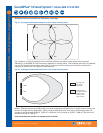
RX22-4 Receiver
Receiver Coverage Area with TX90
Transmitter in Single Channel Mode
RX16 Receiver
RX14-2 Receiver
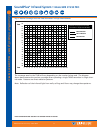
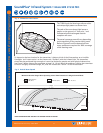
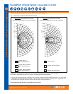
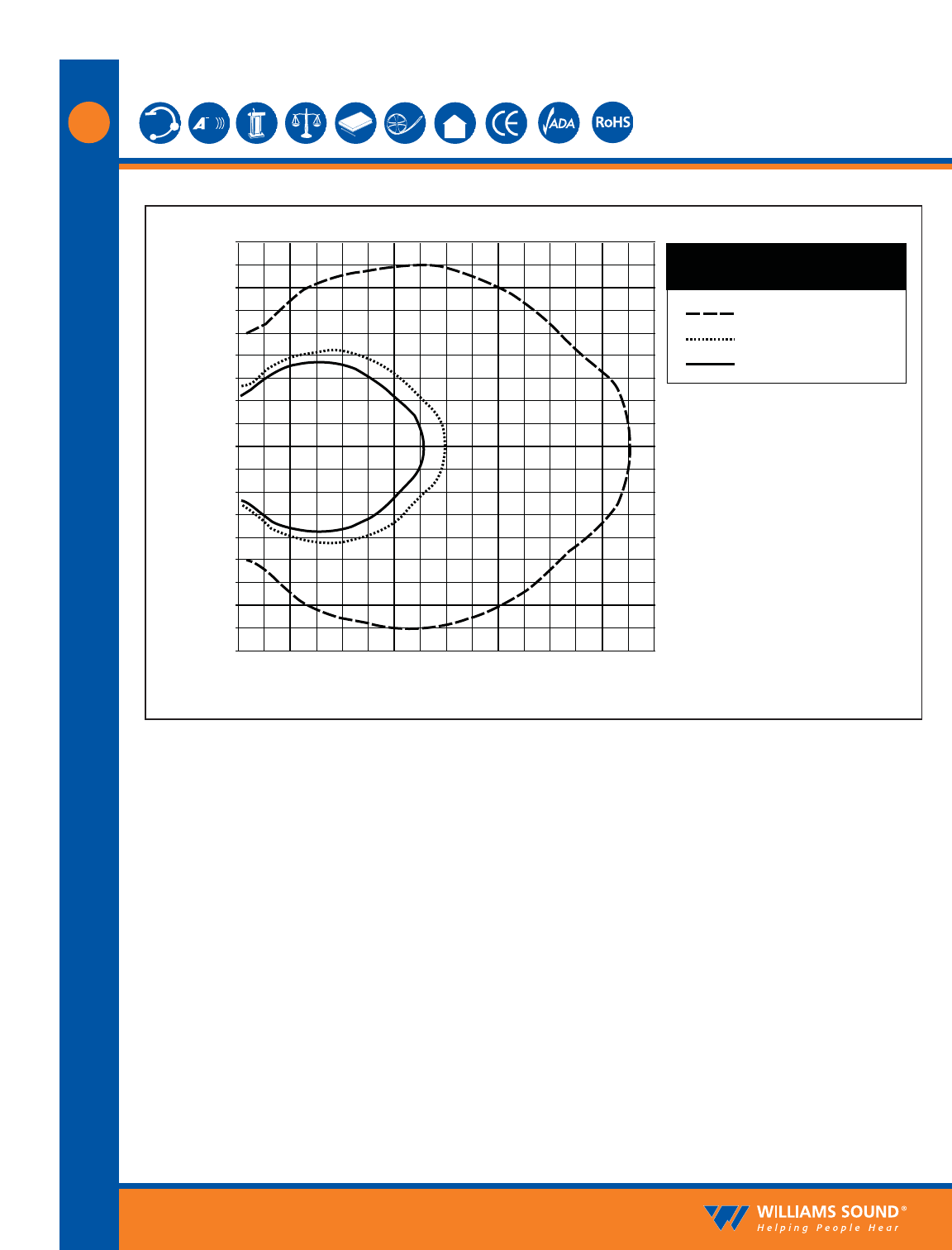
Fig. 3: Receiver Coverage Area with TX90 Transmitter in Single Channel Mode
The coverage area for the TX90 will vary depending on the receiver being used. The diagram
above demonstrates the receiver coverage when operating a single TX90 transmitter in single chan-
nel mode. Patterns are direct radiation patterns.
Note: Reflections of the infrared light from walls, ceilings and floors may change these patterns.
RX22-4
RX14-2
RX16
©2008, Williams Sound Corp. MCAT 065A
3