


5
.
www.velodyne.com
VX-11 User’s Manual
1
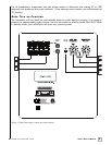
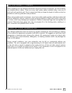
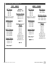
SPEAKER LEVEL OUTPUT terminals
The speaker-level signal to the front speakers is distributed from
t
hese terminals.
2 SPEAKER LEVEL INPUT terminals
Connect these input terminals to the speaker output terminals
of your amplifier or receiver.
3 LINE INPUT jacks
Connect these jacks to the LINE OUT jacks of the amplifier.
4 VOLUME LEVEL knob
Use this knob to adjust the output level of the subwoofer.
5 Power indicator
Red: Unit is in standby mode.
Green: Unit is in operation mode.
(automatically turns to STANDBY mode if no signal for eight min.)
6 LOW-PASS CROSSOVER
Use this knob to select the high-frequency range at which you wish
to cut-off the signal to the subwoofer.
7 PHASE SWITCH
Use this switch to invert the phase of the subwoofer to create a better
blend with your satellite speakers.
Crossov ers
Receiver/Processor Subwoofer Outputs
The Velodyne subwoofer is designed to operate using the full range audio signal for input when
using the built-in crossover. Many home theater processors/receivers (Dolby Digital™, DTS™,
THX™) have a “subwoofer out” jack (sometimes labeled “LFE”) that is internally filtered, settable
at the r
eceiver/pr
ocessor
, and designed to be used with a power
ed subwoofer
. In some
installations, it may be beneficial to use BOTH the Velodyne crossover and the
receiver/processor crossover, resulting in a steeper ultimate crossover slope. In some rare
cases, combining both an exter
nal cr
ossover and the one internal to the subwoofer may result
in low output and increased noise. In these installations you may need to bypass the crossover
in either the processor or your VX-11 subwoofer. Or, simply set one crossover to a higher
frequency (such as 120 Hz) will restore maximum performance.
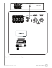
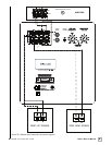
(Refer to Figure 2a Line-Level Subwoofer Connection Diagram and Figure 2b Speaker-Level
Subwoofer Connection Diagram, pages 7 and 8 for connection diagrams.)