


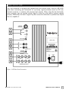

Rear Panel Connections - Detailed Explanations
5
.
www.velodyne.com
VDR Series User’s Manual
(
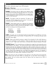
8) SPEAKER LEVEL OUTPUT Terminals
Sends a crossed-over speaker-level signal to the front speakers. See below for a more
d
etailed explanation of this crossover.
Your new subwoofer is equipped with both speaker-level and line-level inputs. Use the
RCA/Phono type “INPUT” jacks when connecting your subwoofer to a pre-amp, signal
processor, or line-level crossover. The “SPEAKER LEVEL INPUT” jacks connect directly to the
speaker outputs of an integrated amplifier or receiver. Your amplifier section will notice no
additional loading effects when you use these inputs because of their high impedance.
Note:
Do not use both the RCA/Phono “INPUT” connections and “SPEAKER LEVEL INPUT”
connections simultaneously.
Low-Pass Crossover
Both sets of inputs sum the left and right channels together and the resulting signal is passed
through an adjustable low-pass crossover before being amplified. The crossover control allows
you to adjust the upper limit of the subwoofer’s frequency response from 60 to 150 Hz. The
subwoofer’s response will begin rolling off above the frequency you set this control to.
You should set the crossover frequency to obtain a smooth and seamless transition from the
subwoofer to the main speakers in your system. If your main speakers are smaller units with
limited low frequency output, you may wish to choose a higher frequency (such as 100 -120 Hz)
than you would with larger speakers which have greater low frequency output. With larger
speakers, you might star
t with this control set lower, such as 80 Hz.
Subwoofer Direct
Subwoofer Direct is a setting on the low-pass cr
ossover knob and will allow fr
equencies up to
200 Hz into the subwoofer. See below for a more detailed explanation of this feature.
Speaker Level Output/Line Level Output
When connected in this fashion, your satellite speakers will be crossed over at 80 Hz. This
removes the lower bass from your satellites, enabling them to do a better job reproducing high
frequencies and giving your receiver’s amp more headroom (up to 50% more power).
Y
ou may also connect your satellites dir
ectly to your r
eceiver or amplifier along with the
subwoofer if you wish to bypass this crossover.
Caution!!!
To avoid damage to your main amplifier, be sure to maintain correct polarity when making all
connections. Red (positive) to red, and black (negative) to black. Be sure that all connections
are tight, and that there are no loose strands or frayed wires.
Power Switch
The master power switch is located on the lower right half of the unit. This r
ocker style
switch is the main on/off for the unit. This switch should be set to position 1 for on (up), 0 for
of
f (down).