


InstallAdvantage IA-400 Amp manual
www.chrysalisacoustics.com
4
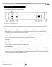
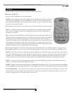
(6) LED Numeric Indicator
This LED supplies information on volume, crossover, woofer type, and other information. The “light” button on the remote deactivates
this display. Upon startup, the display shows the “IW”, referring to the IA-IWS1 subwoofer that the IA-400 amp is controlling, then
reverts to the volume indicator.
(7) Volume Control
These buttons allow you to balance the output from the subwoofer to the main speakers in your system. The volume should be set to
achieve similar volume level of both the main speakers and subwoofer. The default volume is 30.
Note: Volume can also be controlled by using the supplied remote.
WARNING: Some manufacturers preset their receivers with the Sub-Out (a.k.a. LFE) channel signal at a minimum level. It is very
important to verify that your receiver Sub-Out channel is set to the same output level as your front right and left channels. Refer to your
receiver manual for the individual channel level adjustment procedure. If your receiver Sub-Out channel is set too low, the subwoofer may
appear to have a weak output, it may sound noisy or distorted, and the Auto On/Off feature may not operate properly.
(8) Optional Rack Mount Ears (Included)
These ears can be attached to the IA-400 amp to allow standard 19” rack mounting.
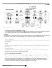
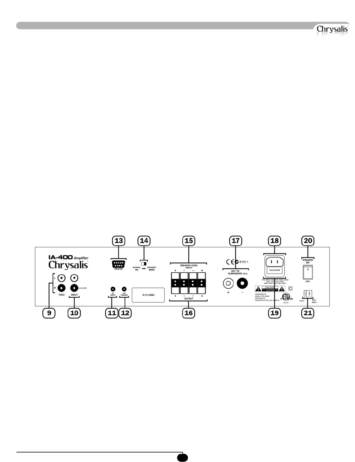
Rear Panel Conections
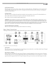
Following are brief descriptions described in Figure 2. More detail on these controls can be found in the next section.
Figure 2: Rear Panel Connections of the IA-400 amplifier.
(9) Thru Jacks
These RCA connectors are for passing along the same signal that goes into your subwoofer to a second “daisy-chained” system. The signal
from these RCA connectors is the same as the input signal.
(10) Line Input / LFE Input
C
o
n
nect these jacks to the LINE OUT preamp output, LFE output, or subwoofer output jacks of your receiver/processor. If using the
LF
E o
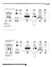
utput from your receiver or processor, plug the single cable into the jack labeled LFE input or, for more signal, use a “Y” connector
(optional) and feed the signal into both “R” and “L” inputs. Examples of these types of connections can be found in Figures 2A and 2B.