


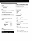
Note:
When the temperature of heat sink exceeds 105°C, the protection
circuit is activated and the output is disconnected from the
circuit. The signal automatically begins to be output as the
temperature goes down. In such a case, confirm whether or not
unit is overloaded or operated on an excessive output.
•
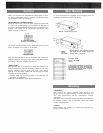
Do not block cover ventilation holes.
•
The amplifier should not be placed in areas;
1. with poor ventilation.
2. exposed to direct sunlight.
3. with high ambient temperature or adjacent to heat-generating
equipment.
4. with high humidity or dusty levels.
5. susceptible to vibration.
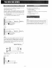
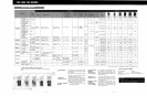
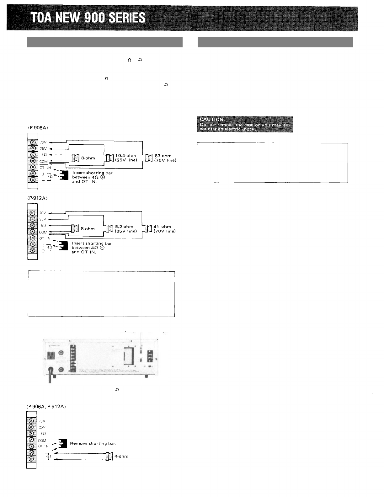
The speaker outputs of the amplifier are 4 , 8 , 25V and 70V.
Connect speakers to one of these outputs.
Class 2 wiring may be used.
Since these outputs consist of 8 , 25V and 70V via the output
transformer (matching transformer) and direct output of 4 , the
connecting method differs in each case. See the following diagrams.
Note: Impedances indicated below imply total speaker system
(load) impedance.
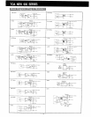
•
When connecting speakers to any one of the outputs of 8 O, 25V
or 70V (BALANCED TRANSFORMER OUTPUT);
Note:
In this case, the LOW-CUT SWITCH should be in "CUT" posi-
tion. This amplifier is characteristically flat even in the low fre-
quency range. Therefore, in TRANS OUTPUT, the acoustic
effect and frequency-response characteristics may be altered.
In TRANS OUTPUT, cut off unnecessary low frequency to ob-
tain the best acoustic condition.
SWITCH in "CUT" position
• When connecting speakers to the 4 output. (UNBALANCED
DIRECT OUTPUT);
Installation
Output Connections P-906A, P-912A
Place
the
LOW—CUT
— 3 —