


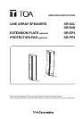
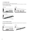
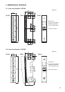

13
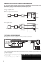
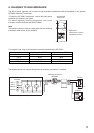
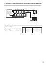
12. INTERNAL WIRING DIAGRAM FOR THE BI-AMPLIFIER DRIVE SYSTEM
The diagram below is an internal wiring after the speaker's drive system is changed to a bi-amplifier system.
LOW +
HIGH +
LOW –
HIGH –
2+
1+
2– 1–
2+
1+
2– 1–
x 4
x 4
Screw terminals Neutrik NL4MP connector
Input terminal panel
Woofers
Tweeters
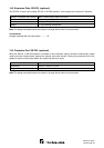
• Since the Neutrik NL4MP connectors and screw terminals are internally connected in parallel, either one can
be used for connection.
• The Neutrik NL4MP connector's pins are wired
as shown at right.
The connector (connection cable side) suited to
the Neutrik NL4MP is the Neutrik NL4FC.
Pin No. SR-S4L, SR-S4S Screw terminal indication
1 + LOW + LOW +
1 – LOW – LOW –
2 + HIGH + HIGH +
2 – HIGH – HIGH –