


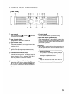
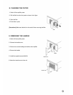
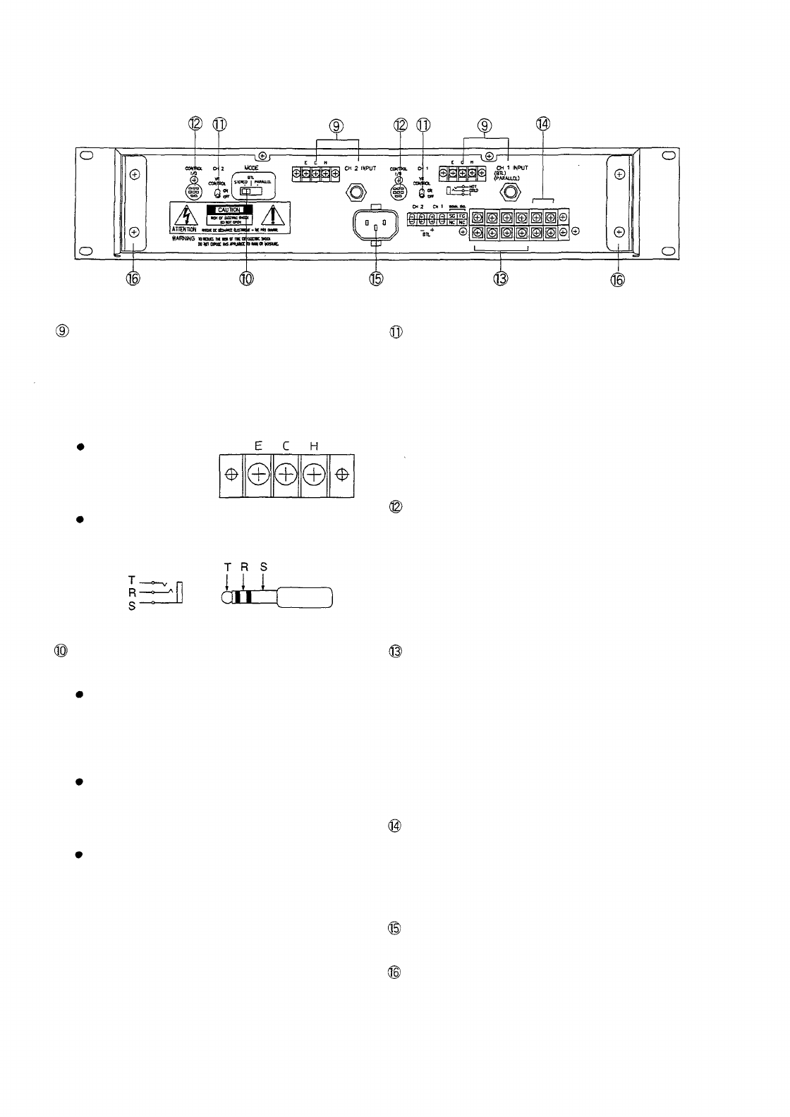
[Rear panel]
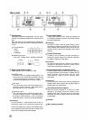
Input terminal
Electrically-balanced input terminals. The 3P screw
terminal is connected in parallel with a balanced phone
jack.
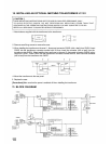
Also, the input can be converted into a transformer-
balanced input using an optional matching transformer
LT-101.
3P screw terminal
H:HOT
C:COLD
E:GROUND
Balanced phone jack
T (Tip): HOT R (Ring): COLD S(Sleeve): GROUND
Phone jack
Phone plug
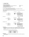
Output mode selector switch
Selects STEREO, BTL or PARALLEL mode.
STEREO mode
Channels 1 and 2 are operated independently. (The
unit functions as a normal stereo amplifier.) Channel
1 input signal goes to Channel 1 output, and
Channel 2 input signal goes to Channel 2 output.
BTL mode
The unit functions as a monaural amplifier with 1
input and 1 output. Channel 1 input signal goes to
both output BTL (+) and (-) terminals.
PARALLEL mode
The unit functions as a monaural amplifier with 1
input and 2 outputs. Channel 1 input signal goes to
the outputs of both Channels 1 and 2. Input signal
levels of channels 1 and 2 can be set independently.
[Precautions]
Use only Channel 1 input terminal when in BTL or
PARALLEL mode. Do not use Channel 2 input terminal.
Confirm the position of the output mode selector switch
before switching on the power. Be sure to switch off the
power when changing mode switch settings.
Level control switch
Usually, set this switch to OFF. When an interface unit
is connected, shifting this switch to ON permits external
input level adjustment.
[Precautions]
No sound is output if the level control switch is set to
ON without connecting an interface unit. Confirm the
switch position before switching on the power. Be sure
to switch off the power when changing control switch
settings.
Control I/O terminal
Connects to the an interface unit when monitoring or
performing remote controls from external equipment.
For details, contact your TOA dealer.
[Precautions]
No other unit other than an interface unit must be
connected to the terminal. Be sure to switch off the
power when connecting an interface unit.
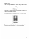
Output terminal (with a protection cover)
Connect speaker cables to these terminals. Because
the upper terminals are connected in parallel with the
lower terminals, both terminals can be used
simultaneously. Refer to p.8 for speaker cable
connections.
[Precautions]
Be sure to switch off the power when connecting the
speaker cables. Never connect two amplifier outputs in
parallel under any circumstances.
Grounding terminal for signals
When the power amplifier is connected to other
equipment, grounding sometimes creates a loop,
producing hum noise. This loop can be cut and noise
reduced by removing a shorting metal piece connecting
two terminals.
A C inlet
Rear mounting bracket
6