8. INPUT SECTION
8.1. HX-5B and HX-5W
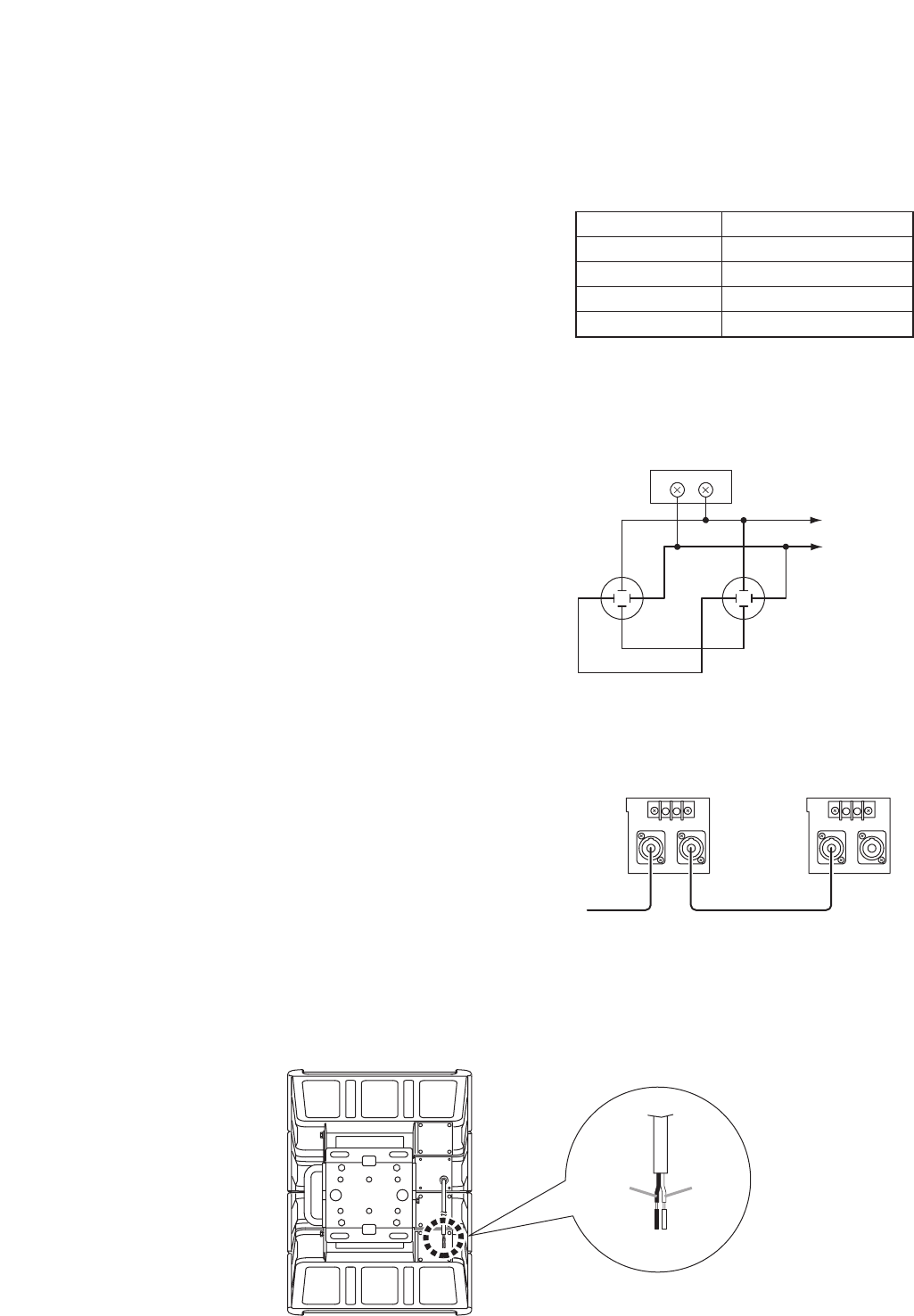
• The 2 Speakon connectors are internally connected in parallel to the screw terminals; you can use either
one.
• The right table shows the pin arrangement of the
Speakon NL4MP connector.
• The usable connector (on the cable end) for the Speakon NL4MP is Speakon NL4FC.
• Wiring diagram of the input connectors is shown at right.
• Two speaker systems can be operated in parallel by
connecting them in a cascade configuration as shown at
right.
Note
Be sure to connect the speaker system to the power
amplifier's output terminal of 4 Ω or less.
Connecting it to an output terminal of over 4 Ω may
cause amplifier failure.
8.2. HX-5B-WP and HX-5W-WP
6
Pin No. HX-5B, HX-5W
1 + Speaker +
1 – Speaker –
2 +
–
2 –
–
Screw terminal 2P
Speakon NL4MP x 2
1+
2+
1–
2–
1+
2+
1–
2–
Speaker +
Speaker –
– +
First speaker Second speaker
[Rear]
White
(–)
Black
(+)


