


8
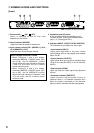
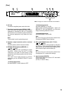
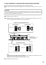
7. NOMENCLATURE AND FUNCTIONS
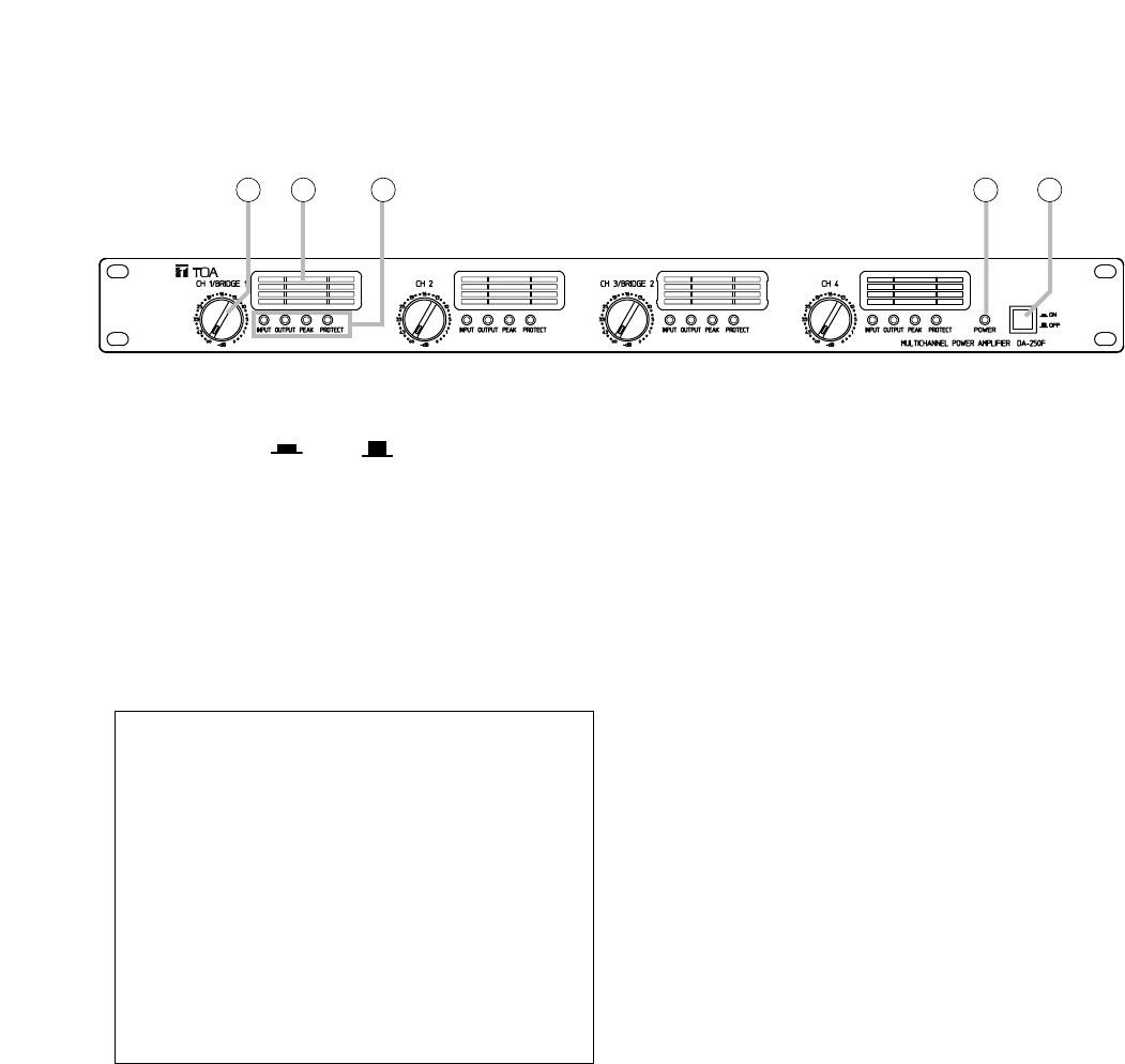
[Front]
1. Power switch [ ON/ OFF]
Power is switched on and off with each
depression of this switch.
2. Power indicator [POWER]
Lights blue when the power is switched on.
3. Input volume controls [CH 1 (BRIDGE 1), CH 2,
CH 3 (BRIDGE 2), CH 4]
Adjust the input volume of each channel.
When a bridge connection is made
• When Channels 1 and 2 are bridge-
connected (BRIDGE 1 ON/OFF button (9) is
set to ON), the CH 1/BRIDGE 1 volume
control adjusts the input volumes of Channels
1 and 2. In this event, the CH 2 volume
control cannot be used.
• When Channels 3 and 4 are bridge-
connected (BRIDGE 2 ON/OFF button (9) is
set to ON), the CH 3/BRIDGE 2 control
adjusts the input volumes of Channels 3 and
4. In this event, the CH 4 volume control
cannot be used.
4. Ventilation panel (Air Vent)
A filter is located inside the ventilation panel.
To clean the filter, remove the ventilation panel.
(See p. 15; Cleaning the Filter.)
5. Indicators [INPUT, OUTPUT, PEAK, PROTECT]
The indicators are as follows from left to right:
• Input indicator [INPUT]
Lights green regardless of the input volume
control setting when an input signal level exceeds
about –20 dB.
• Output indicator [OUTPUT]
Lights yellow when an output level exceeds about
1W at an 8 Ω load (DA-250F) or 19.6 Ω load (DA-
250FH).
• Peak indicator [PEAK]
Lights red when an output signal clips (distortion
occurs).
• Protection indicator [PROTECT]
Lights red when the protection circuitry is
activated. (See p. 14; Protection Operation List.)
When the power is switched on, this indicator
lights for about 2 seconds and then extinguishes.
1243 5
Note: The figure shows the DA-250F.