


www.ti.com
1.2TPA3100D2EVMSpecifications
2Operation
2.1QuickStartListforStand-AloneOperation
Operation
V
CC
Supplyvoltagerange10Vto26V
I
CC
Supplycurrent4Amax
P
O
Continuousoutputpowerperchannel,8Ω,V
CC
=18V,THD+N=3.5%20W
R
L
Minimumloadimpedance3.2Ω
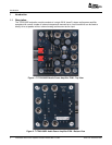
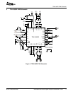
FollowthesestepstousetheTPA3100D2EVMstand-aloneorwhenconnectingitintoexistingcircuitsor
equipment.ConnectionstotheEVMmodulecanbemadeusingbananaplugsforthepowersupplyand
outputconnections.TheinputsacceptstandardRCAplugs.
2.1.1PowerSupply
1.EnsurethatallexternalpowersourcesaresettoOFF.
2.Connectanexternalregulatedpowersupplyadjustedfrom10V–26VtothemoduleV
CC
(J7)and
GND(J8)bananajackstakingcaretoobservemarkedpolarity.
2.1.2EvaluationModulePreparations
2.1.2.1InputsandOutputs
1.Ifconnectingtoafullydifferentialinputoragroundedinput(theshieldoftheRCAjackisGND),
removejumpersJ9andJ10fromtheEVMboard.ThesearelocatednexttotheinputjacksJ1andJ2.
Ifconnectingtoafloatingsource,likeaportableCDplayer,installJ9andJ10.AftersettingtheJ9and
J10jumpersappropriately,connecttheaudiosourcetoJ1(RIGHT)andJ2(LEFT).
2.ConnectaspeakeracrossROUT+(J6)andROUT-(J5).ConnectanotherspeakeracrossLOUT+(J3)
andLOUT-(J4).
3.InstallbothgainjumpersGAIN0(J12)andGAIN1(J13).Thissetsthegainoftheamplifiertothe
lowestlevel,20dB.
4.RemovethejumperatMSTR/SLV(J14).IfonlyoneTPA3100D2isevaluated,itmustbeconfiguredas
themaster.IfmultipleEVMsareconnectedtogetherusingtheSYNCoutput(TP2),theadditional
EVMsmustbeconfiguredintheslavemodebyinstallingtheJ14jumper.
5.Removethejumper(J11).Thisplacesthedeviceinalatchedmodewhenashort-circuiteventoccurs.
2.1.2.2ControlInputs
1.SD:Thisterminalisactivelow.Alowsignalonthedeviceterminal(<0.8V)shutsdowntheamplifier;
ahighsignal(>2V)onthedeviceterminalplacestheamplifierintheactivestate.Holdingdown
switchS1placestheamplifierintheSHUTDOWNstate.ReleasingS1returnstheamplifiertothe
activestate.
2.MUTE:Thisterminalisactivehigh.Ahighsignal(>2V)onthisterminalimmediatelyterminatesaudio
playbackthroughthespeakersandtheoutputsstopswitching;alowsignal(<0.8V)enablesthe
device.S2ontheEVMcontrolsthestateoftheMUTEterminal.HoldingdownswitchS2placesthe
amplifierintheMUTEstate.ReleasingS2returnstheamplifiertotheactivestate.
3.GAIN0/GAIN1:Together,theseterminalsdeterminethegainoftheamplifier.RefertoTable1.
InstallingajumperinJ12orJ13setstherespectiveterminaltoGND.Removingthejumpersetsthe
respectiveterminalstoVREG(~4V).RemovingjumpersINCREASESthegainwhileinstallingjumpers
DECREASESthegain.LogiclevelsareTTLcompatible.
4.MSTR/SLV:ThisterminalisusedwiththeSYNC(TP2)outputtosynchronizetheswitching
frequenciesofmultipleTPA3100D2devices.Forexample,with2devices,onewouldbeconfiguredas
theMASTERbyremovingtheJ14jumper.TheotherEVMwouldbeconfiguredastheSLAVEdevice
byinstallingajumperintheJ14location.LogiclevelsareTTLcompatible.
SLOU179–December2005TPA3100D2AudioPowerAmplifierEvaluationModuleWithLCFilter3