


Using the TPA102 MSOP EVM With the Plug-N-Play Evaluation Platform
3-7
Details
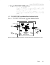
3.3.2 Signal Routing
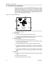
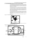
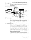
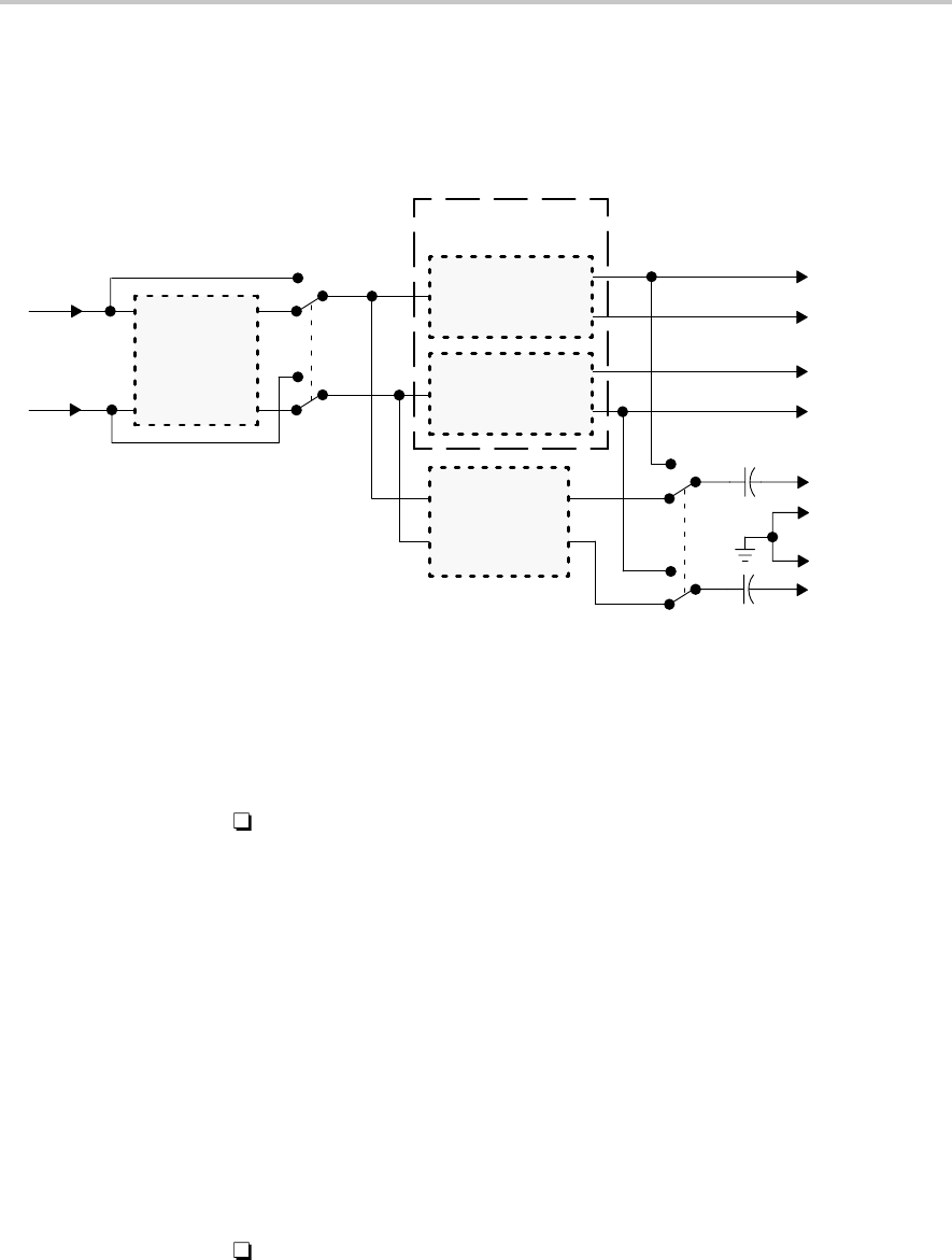
Signal flow on the platform is controlled by two signal routing switches, as
shown in Figure 3–5.
Figure 3–5. Platform Signal Routing and Outputs
U1
Signal
Conditioning
On
Off
U5
TPA102 MSOP
Headphone
Amplifier EVM
S2
R
L
R
L
L
U5
U2–U4
S3
J10
Headphone
Output
R
L
Audio
Input
R
L
J7, J8, J9
Speaker
Outputs
R
+
+
–
–
U3
Mono Power
Amplifier EVM
+
+
–
–
U4
Mono Power
Amplifier EVM
GND
U2 Stereo Power
Amplifier EVM
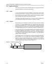
3.3.2.1 Signal Conditioning
The audio signal from the input jacks can be applied to the signal conditioning
socket (U1) if an EVM is installed there, or socket U1 can be bypassed and the
audio input signal applied directly to the inputs of the TPA102 power amplifiers.
Switch S2 selects or bypasses signal conditioning.
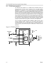
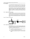
3.3.2.2 Headphone Output Jack
Switch S3 is the source select for the stereo headphone output jack, J10. The
headphone jack is capacitively coupled (via 470 µF electrolytics. It can output
either the signal from the the TPA102 MSOP headphone amplifier in socket
U5, or the signal from power amplifiers installed in socket U2 or in sockets U3
and U4, as determined by the setting of headphone source select switch S3.
When S3 is set to the headphone amplifier position (U5), the headphone jack
is connected to the headphone amplifier EVM output lines. When a plug is
inserted into the jack, signals output through J10 are returned to platform
ground. A switch inside the headphone jack produces a control signal that can
be routed to the headphone amplifier socket to shutdown the TPA102 MSOP
EVM when the headphone plug is removed.
Switch S3 connects the headphone jack to either the headphone amplifier
platform socket (U5) or to the platform power amplifier sockets (U2 – U4).