


2-4
Using the THS4151 EVM
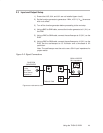
2.4 Testing the EVM Setup
1) Turn on the dc power supply.
2) Verify that both the +5 V (current meter 1) and the –5 V (current meter 2)
currents are below 20 mA.
Caution:
Currents above 20 mA indicate a possible short or a wrong resistor value
on the PCB. Do not proceed until this situation is corrected.
3) Turn on the function generator.
4) Verify the oscilloscope is showing two 1 MHz sine waves with amplitude
of ±0.125 V. The dc offset of the signal must be below 50 mV.
Note: V
OUT+
and V
OUT–
should be 180 degrees out of phase. The internal
attenuation of the scope should be set to 6 dB for a gain of one. Otherwise,
the output will show a
gain of one-half
due to the voltage division occurring
at the 50-Ω termination resistor.
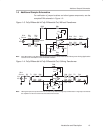
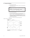
Use Figure 3 as a reference for the input and output signals.
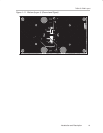
Figure 2–3. Driver 1 Output Signal
THS4151
C3
C2
C1