


2-2
Using the THS4151 EVM
2.1 Required Equipment
One double-output dc power supply (±5 V, 100 mA output minimum)
Two dc current meters with resolution to 1 mA and capable of the
maximum current the dc power supply can supply. If available, set the
current limit on the dc power supply to 100 mA.
Note: Some power supplies incorporate current meters which may be
applicable to this test.
50-Ω source impedance function generator (1 MHz, 10 V
PP
sine wave)
Oscilloscope (50-MHz bandwidth minimum, 50-Ω input impedance).
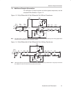
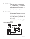
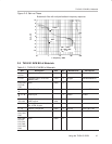
2.2 Power Supply Setup
1) Set the dc power supply to ±5 V.
2) Make sure the dc power supply is turned off before proceeding to the next
step.
3) Connect the positive (+) terminal of the power supply to the positive (+)
terminal of the current meter number 1.
4) Connect the negative (–) terminal of the current meter number 1 to the
V
CC+
of the EVM (J7).
5) Connect the common ground terminal of the power supply to the ground
GND on the EVM (J9).
6) Connect the negative (–) terminal of the power supply to the negative (–)
terminal of the second current meter.
7) Connect the positive (+) terminal of the current meter number 2 to the V
CC–
of the EVM (J8).
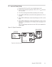
Figure 2–1. Power Supply Connection
POWER SUPPLY
GND–5V +5V
+– +–
CURRENT
METER 2
CURRENT
METER 1
J8 V
CC–
J9 GND
J7 V
CC+
J6 V
OCM
EVM
THS4151
Figures are not drawn to scale.