


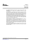

2.1PowerSupply(PSU)Interface(J901andJ900)
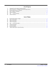
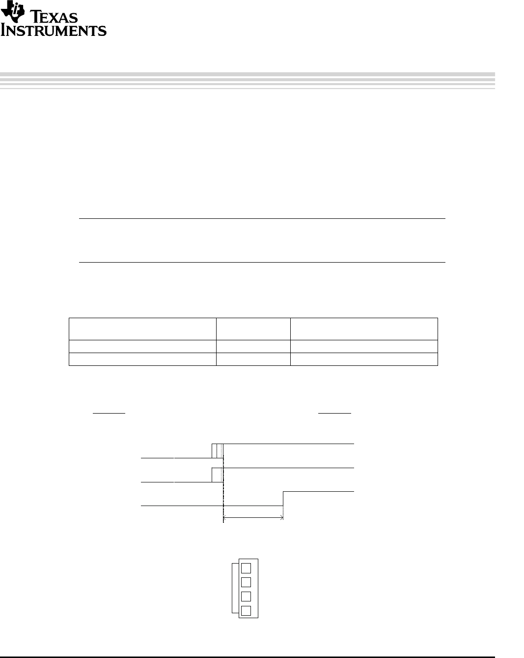
Outputstagepowersupply
RESET
>1ms
Systempowersupply
4
1
2
3
(PCBconnectortopview)
Chapter2
SLEU071–June2006
SystemInterfaces
ThischapterdescribestheTAS5508-5142K7EVMboardinregardstopowersupplies
andsysteminterfaces.
TheTAS5508-5142K7EVMmodulemustbepoweredfromexternalpowersupplies.High-endaudio
performancerequiresastabilizedpowersupplywithlowripplevoltageandlowoutputimpedance.
Note:Thelengthofpower-supplycablemustbeminimized.IncreasinglengthofPSUcableis
equaltoincreasingthedistortionfortheamplifierathighoutputlevelsandlow
frequencies.
Maximumoutput-stagesupplyvoltagedependsofthespeakerloadresistance.Pleasecheckthe
recommendedmaximumsupplyvoltageintheTAS5142datasheet.
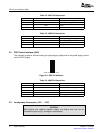
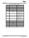
Table2-1.RecommendedSupplyVoltages
VOLTAGE
DESCRIPTIONCURRENTRECOMMENDATIONS
LIMITATIONS
Systempowersupply15Vto20V0.3A
Output-stagepowersupply0Vto32V6A
(1)
(1)
Theratedcurrentcorrespondto2-channelfullscale(80Weach),whichmostlikelyisadequatefor
astandard8-channelamplifierdesign.
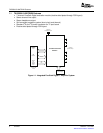
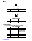
TherecommendedTAS5142power-upsequenceisshowninthefigurebelow.ForproperTAS5142
operation,theRESETsignalshouldbekeptlowduringpowerup.RESETispulledlowduringpowerup
for200msbytheonboardresetgenerator(U73).
Figure2-1.RecommendedPower-UpSequence
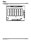
Figure2-2.J901andJ900PinNumbers
SLEU071–June2006SystemInterfaces9
SubmitDocumentationFeedback