


2-3
Using the THS4140 EVM
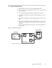
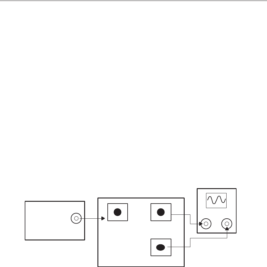
2.3 Input and Output Setup
1) Ensure that JU3, JU4, and JU1 are
not installed
(open circuit)
.
2) Set the function generator to generate a 1 MHz, ±0.5 V (1 V
PP
) sine wave
with no dc offset.
3) Turn off the function generator before proceeding to the next step.
4) Using a BNC-to-SMA cable, connect the function generator to J1 (V
I+
) on
the EVM.
5) Using a BNC-to-SMA cable, connect the oscilloscope to J3 (V
O–
) on the
EVM.
6) Using a BNC-to-SMA cable, connect the oscilloscope to J4 (V
O+
) on the
EVM. Set the oscilloscope to 0.5 V/division and a time-base of 0.2
µs/division.
Note: The oscilloscope must be set to use a 50-Ω input impedance for
proper results.
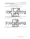
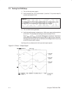
Figure 2–2. Signal Connections
OUT
1 MHz
1 V
PP
0 V Offset
50 Ω Source
Impedance
J1 V
in+
J3 V
out–
J4 V
out+
CH-1 CH-2
THS4140 EVM
FUNCTION
GENERATOR
OSCILLOSCOPE
50 Ω Impedance
Figures are not drawn to scale.