


Additional Sample Schematics
1-5
Introduction and Description
1.6 Additional Sample Schematics
For verification of jumper locations and other bypass components, see the
complete EVM schematic in Figure 1–2.
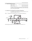
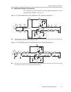
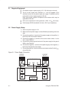
Figure 1–3. Fully-Differential In/Fully-Differential Out, Without Transformer
+
–
THS4140
–
+
V
CC
V
CC–
V
IN
AC
0 Ω
0 Ω
RX1
0 Ω
RX2
R1b
R1a
R6a
C1
V
OCM
C4
C6
R4b
R4a
0 Ω
0 Ω
Rx4
Rx5
R10
Rx6
50 Ω
Source
R3B
0 Ω
0 Ω
0 Ω
R16 Termination
Resistor
R3a
R6b
Note: Fully-differential in / fully-differential out signal path.
See the Texas Instruments February 2001 Analog Applications
Journal for the information on the termination resistors
.
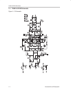
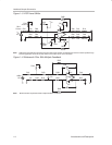
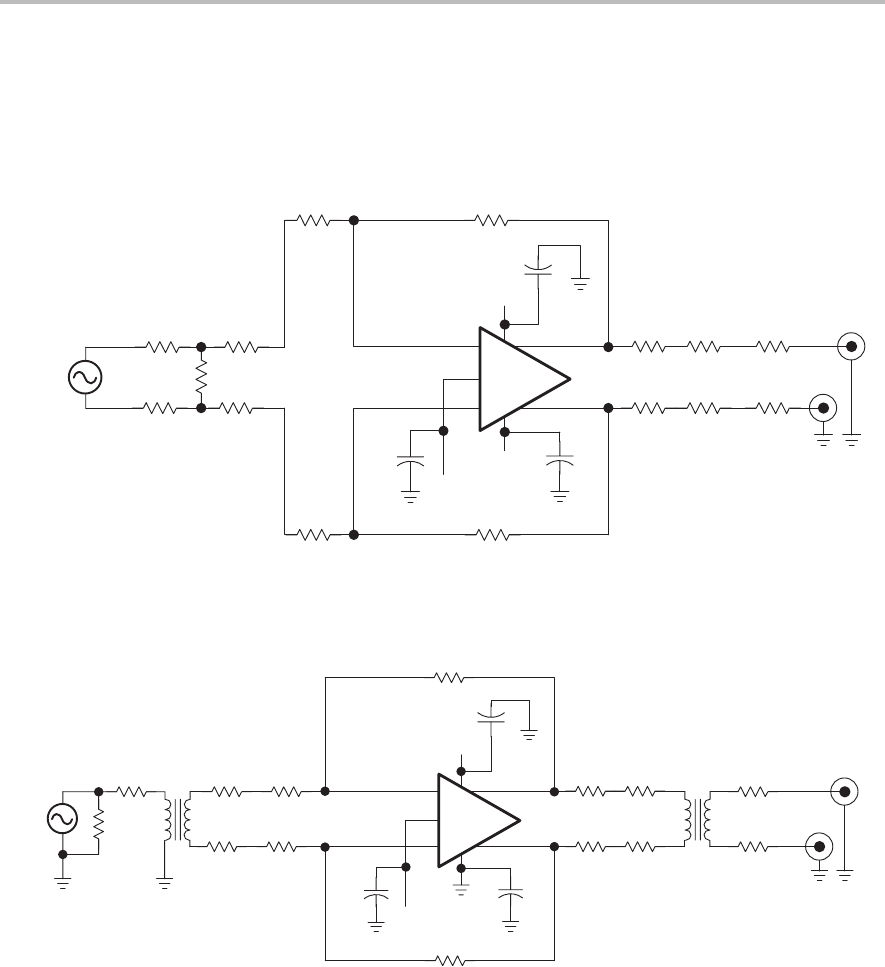
Figure 1–4. Fully-Differential In/Fully-Differential Out, Utilizing Transformer
+
–
THS4140
–
+
V
CC
GND
V
IN
AC
0 Ω
0 Ω
R1B
R1A
R3b
R3a
R6a
C1
V
OCM
C4
C6
R4b
R4a
0 Ω
0 Ω
R14
R15
R10
Rx6
50 Ω
Source
R6b
R5
R9
T1 T2
Note: Utilizing the input and output transformers to create a fully-differential signal input/ differential or single output and isolate
the amplifier from the rest of the front-end and back-end circuits.