


EQUIP MENT SET-UP AND OPERATION
TT-16 SYNTHESIZED
TRANSMITTER
UN PACKING: Un pack your Wire less IFB sys tem. If
there are any dam ages or short ages, re fer to the "War -
ranty Ser vice In for ma tion" card.
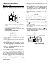
TT-16 TRANS MITTER LO CA TION: Se lect a suit -
able lo ca tion for the TT-16 Trans mit ter. Try to keep a
clear, un ob structed path be tween the trans mit ter and
re ceiver and al low plenty of free space around the
trans mit ter an tenna.
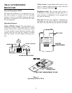
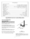
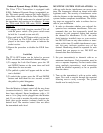
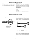
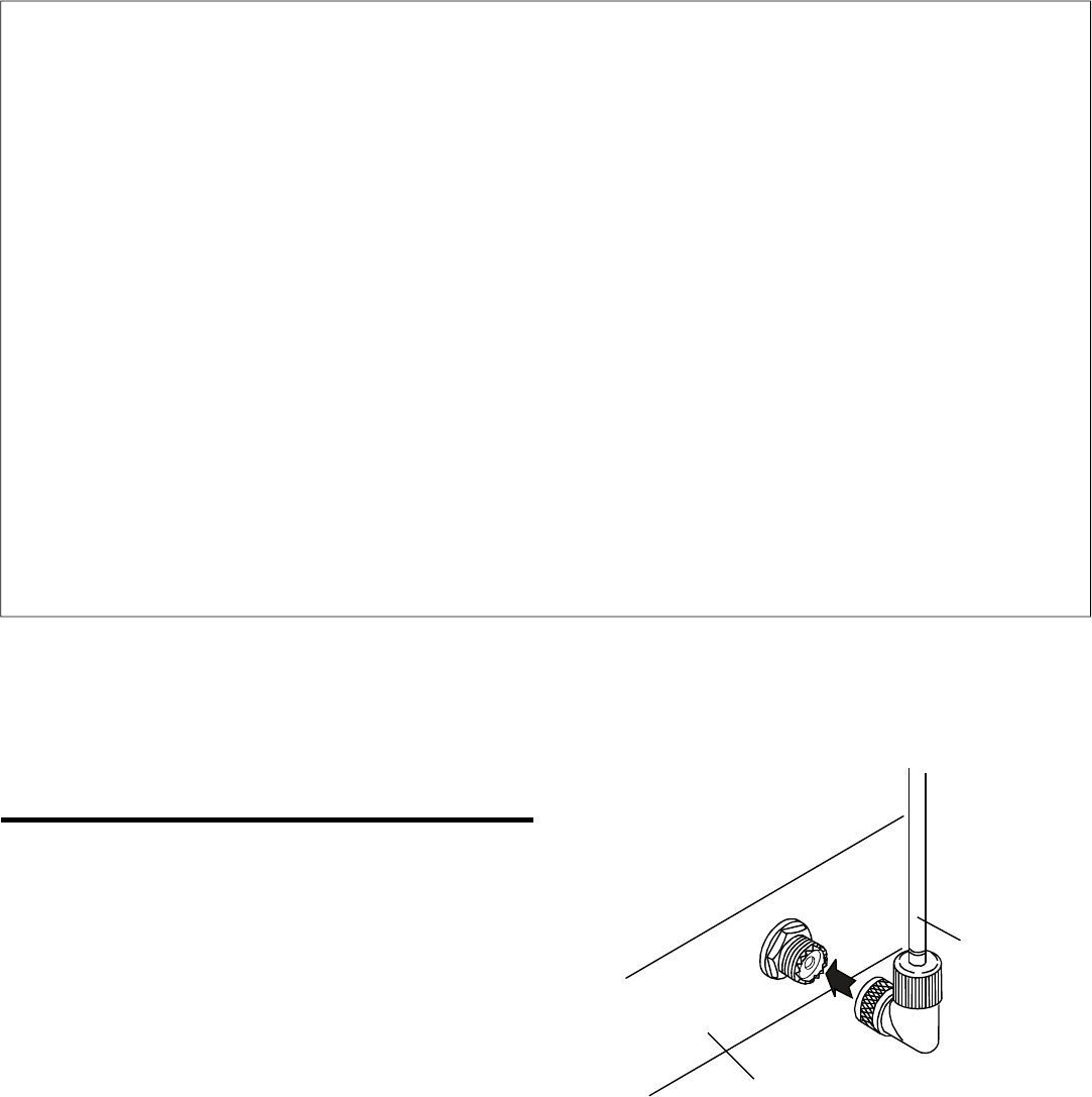
AN TENNA CON NEC TIONS: Con nect the tele -
scop ing an tenna to the rear panel AN TENNA jack.
For best re sults, the an tenna should be ver ti cally
aligned. Tighten the knurled ring to hold the an tenna
in place, and ex tend the an tenna to full length.
Fig ure 6
An tenna Connection
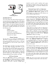
POWER CON NEC TION: Plug the AC power
adapter into an elec tri cal out let. Plug the other end
of the cord into the power in put jack on the rear
panel of the TT-16.
-6-
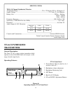
TT-16 Spec i fi ca tions
Au dio In put: Fe male XLR
RTS 1 Se lected........................................................................Line im ped ance 200 Ω / Level ad just able
RTS 2 Se lected........................................................................Line im ped ance 200 Ω / Level ad just able
Telex Se lected.........................................................................Line im ped ance 300 Ω / Level ad just able
Un bal anced Au dio In put ..................................10K Ω in put im ped ance/10 mV-1.0 VRMS in put range
RF Power Switch.......................................................................50mW in “Hi”, approx. 5mW in “Low”
AGC Range ......................................................................................................................................30 dB
Sig nal-to-noise Ra tio:
Nor mal..........................................................................................................................................58 dB
EDR En abled................................................................................................................................77 dB
Pre-Em pha sis....................................................................................................................................115µS
Max i mum De vi a tion.....................................................................................................................±25 kHz
Fre quency Con trol Crys tal.........................................................................................+/-.005% tol er ance
Avail able Fre quen cies ................................................................................................See Ta ble 1, page 2
Max. Trans mit ter Out put Power....................................................................................................50 mW
Power Re quire ments ................................................................................12-15V, AC or DC @ 300 mA
Di men sions...................................................................................................7 ½"W x 1 3/4"H x 6 7/8"D
FCC ID......................................................................................................................................B5DM524
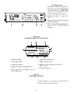
REAR PANEL
ANTENNA