


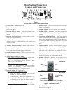
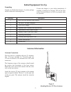
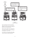
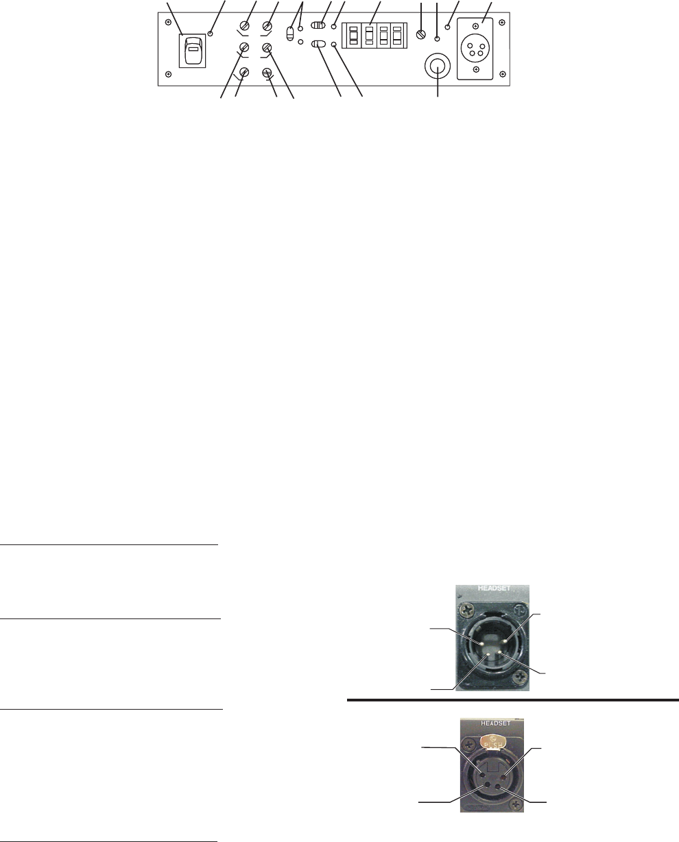
Base Station Transceiver
Controls and Connections
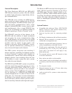
1. Power Switch - Illuminates when on.
2. Beltpack Light - Illuminates when a beltpack is transmit-
ting to base station.
3. Intercom In Level Control - Adjust for optimum level.
Intercom light #11 should just flash red on loudest
speech.
4. Intercom Out Level Control - Adjusts output to match
input level of wired intercoms.
5. Auxiliary In Level Control - Adjust for optimum level.
Auxiliary light #13 should just flicker from green to red
on loudest sounds.
6. Auxiliary Out Level Control - Adjusts output to match
input level of auxiliary equipment.
7. Sidetone Local Control - Adjusts level of voice feedback
to earphone when a headset is plugged into jack #18.
8. Sidetone Remote Control - Controls sidetone level in the
beltpack.
9. Audio Channel Switch And Lights -
A. “I/C” switch on rear panel set to Telex
- Selects either
“I/C 1 or 2" jack (and corresponding pins on ”I/C Loop
Thru"). In “Auto” position; allows selection of chan-
nels 1 or 2 from the beltpack.
B. “I/C” switch on rear panel set to RTS
- Selects RTS
channel 1 or 2 on both I/C jacks (and corresponding
pins on “IC Loop Thru”). In “Auto" position; allows
selection of channels 1 or 2 from the beltpack.
10. Intercom Switch - See settings below.
A. “I/C” switch on rear panel set to “Telex”
1. “Telex Out” Setting - Intercom is disconnected
from all “I/C” jacks on rear panel.
2. “Telex In” Setting - Intercom is connected to “I/C
Loop Thru” and “I/C 1 or 2" jacks. Channel 1 or 2
is selected by switch #9 or the channel switch on
the beltpack.
B. “I/C” switch on rear panel set to “RTS”
- Switch has no
effect. All I/C jacks on rear panel are active on either
setting.
11.
Intercom Light - Flashes red when input level is too high.
See #3 for adjustment.
12. Auxiliary Switch - Turns the auxiliary input on and off.
13. Auxiliary Light - Illuminates green when switch #12 is
on. Flashes red when input level is too high. See #5 for ad-
justment.
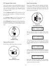
14. Code Switch (BTR-600C Only) - Allows user to select
cipher code (over 65,000 available). Any combination of
letters and/or numbers may be selected except 0000. Data
is unencrypted when the setting is 0000. The code switch
settings on the BTR-600C and TR-600C must match ex-
actly.
15. Volume, Headset - Controls volume on headset plugged
into #18
16. Talk/Overmodulation Light - Illuminates green when
talk switch #19 is on. Flashes red when headset micro-
phone is over modulated - See #17 for adjustment.
17. Microphone Gain Control - Adjust so that light #16 just
flickers from green to red on the loudest speech.
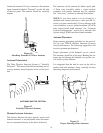
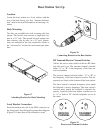
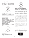
18. Headset Connector - Standard “XLR” type. Plug for
Telex units and jack for RTS units. Wired as follows:
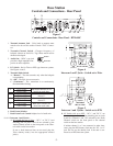
Figure 2 Headset Wiring
19. Talk Switch - Press-to-talk, release to disable. Press and
release quickly to stay on.
-2-
A
1
B
2
RadioCom
ON
OFF
E
B
L
T
A
P
C
K
LOCAL
BELT PACK
SIDETONE
AUX
OUT
IN
IN
OUT
I/C
AUDIO
CHANNEL
AUTO
1
2
I/C
TELEX
IN
OUT
AUX
OFF
ON
VOL
TALK
GAIN
MIC
HEADSET
TAL K/
OM
CODE SWITCH
A
1
B
2
RadioCom
ON
OFF
E
B
L
T
A
P
C
K
BTR-600C
LOCAL
BELT PACK
SIDETONE
AUX
OUT
IN
IN
OUT
I/C
AUDIO
CHANNEL
AUTO
1
2
I/C
TELEX
IN
OUT
AUX
OFF
ON
VOL
TALK
GAIN
MIC
HEADSET
TAL K/
OM
CODE SWITCH
TM
123
49
10
11 14
15
17 18
57
86
12
13
19
16
(1) Microphone
Shield (-)
(2) Microphone
Audio (+)
(4) Headphone
Low (-)
(3) Headphone
High (+)
(1) Microphone
Shield (-)
(2) Microphone
Audio (+)
(4) Headphone
Low (-)
(3) Headphone
High (+)
Figure 1
Front Panel Controls and Connections
Telex Units
RTS Units