


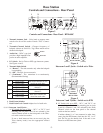
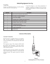
Base Station Set-Up
Location
Locate the base station on a level surface with the
rear of the unit facing you. See “Antenna Informa-
tion” section for more information on choosing a lo-
cation.
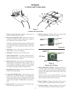
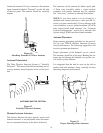
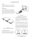
Rack Mounting
Two kits are available for rack mounting the base
station. The first kit rack mounts a single base sta-
tion in a 19" rack. The second kit rack mounts two
base stations, side by side, in a 19" rack. Instruc-
tions are included in the rack mount kits. Refer to
the “Accessories” section for rack mount part num-
bers.
Figure 17
Attaching Brackets for Rack Mounting
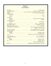
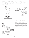
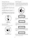
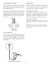
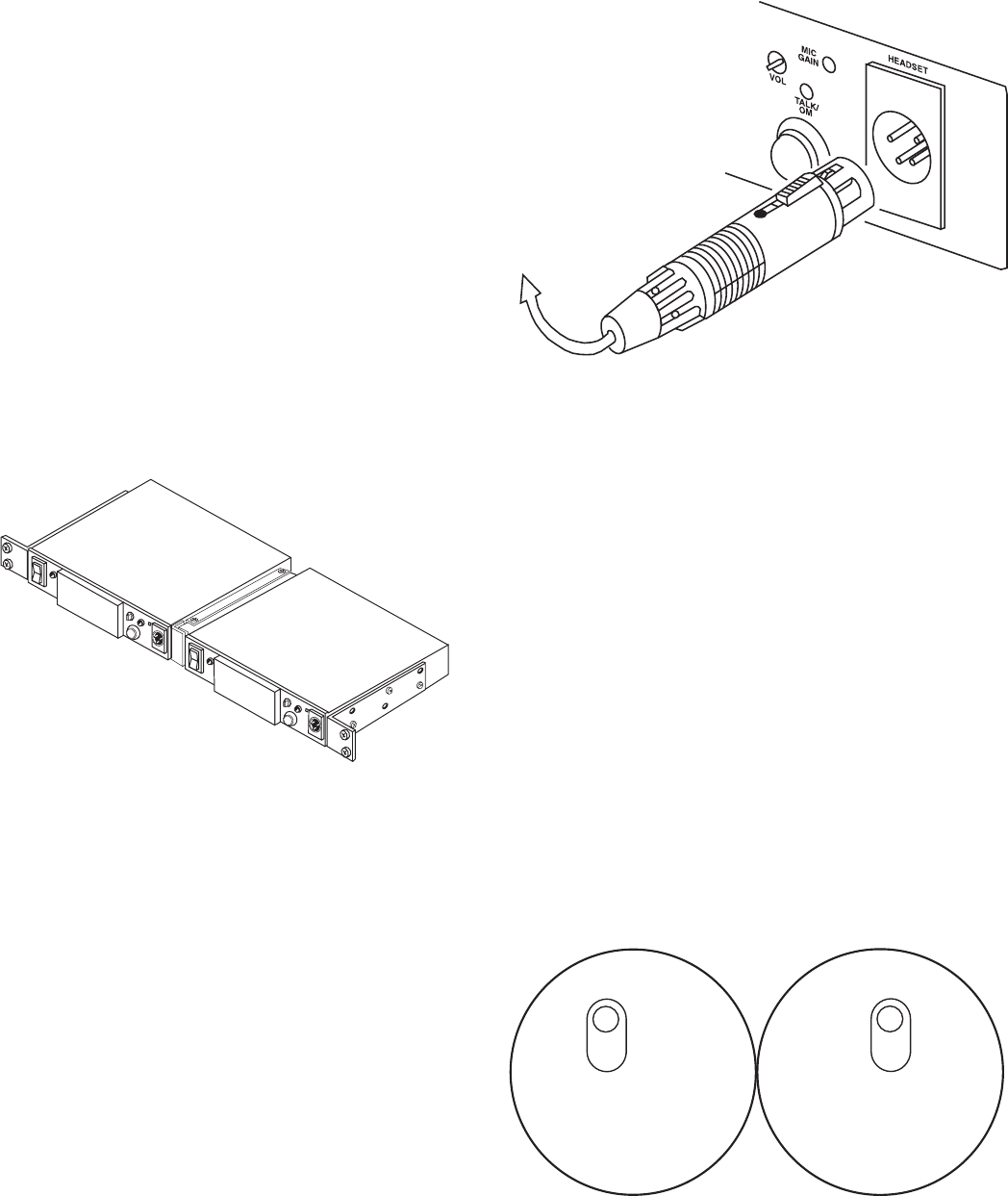
Local Headset Connection
Insert the headset into the 4 pin XLR connector on
the front panel. See the headset connection diagram
(Figure 2) if other than a Telex Headset is used.
Figure 18
Connecting Headset to the Base Station
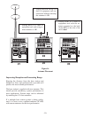
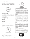
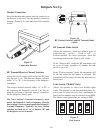
RF Transmit/Receive Channel Switches
Allows the user to select which of the two RF chan-
nels the unit is on. The transmit channel selected,
either “A” or “B”, is the frequency of the base sta-
tion’s transmitter.
The receiver channel selected, either “A” or “B”, is
the frequency of the base station’s receiver. The fre-
quencies are listed on the bottom of the base station.
The base station’s transmit frequency must match
the beltpack’s receive frequency. The base station’s
receiver must match the beltpack’s transmit fre-
quency. Typically both base station switches are set
to “A” or both to “B” and the beltpacks are set to
the same.
Figure 19
Receive and Transmit Switches
-11-
TRANSMIT
CHANNEL
A
B
RECEIVE
CHANNEL
A
B