9
Operation
method of determining the proper Address switch setting varies for each intercom system. Use the method for your intercom
system as described below. Then set the white point on the Address switch to point to the correct setting.
Address Setting for Zeus
Intercom port connectors on the Zeus back panel are arranged in three groups of eight intercom ports. For each group,
intercom port connectors are labeled ID1, ID2, etc. When you connect a PAM-32 keypanel to Zeus, set the Address switch to
match the corresponding ID number on the Zeus backpanel. Note, the address switch setting 0 and 9 through F are not used.
Address for ADAM CS
Each Audio I/O card contains 1 group of intercom ports. However, the method of breaking out the groups depends on the type
of connectors on the back panel.
ADAM CS with RJ-12 or DB-9 back panel:
The intercom port connectors are arranged in groups of 8. The first connector at the left for each group is Address 1, the next is
Address 2, and so forth.
NOTE: Address switch settings 0, and 9 through F are not used.
Address Setting for Adam
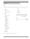
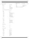
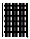
Each Audio I/O card contains 1 group of 8 intercom ports. Determine the address setting from Figure X. To use the table,
locate the intercom port number to which the PAM-32 Address will be connected. Then, read across the Address column to
find the Address number.
PAM-32 Addressing
A rotary switch is used to indicate the logical port address the key panel is to use when communicating with the Matrix. The
switch is read continuously through polling by the matrix. If the port address is changed, the new address is not seen on a
powered unit until the power is recycled.
NOTE: The Address port, by default, is shipped with an invalid address to ensure that there are no conflicts with existing
keypanels. It is important to set the address port for the KP-32 keypanel for it to function properly.
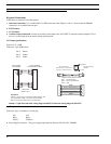
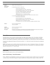
In Zeus, ADAM CS, and ADAM intercom system, intercom ports are arranged in groups of 8. Within each group, each
keypanel is uniquely identified by its Address switch setting. In the below example, the Address switch has a white pointer
pointing at position 7, indicating port 7.
Operation
Operation is identical for each keypanel.
Listen Key Operation
ONE Mode: ONE mode gives preference to a single active key. Tap a key to turn it on. The green LED lights. When you tap
another key, the first key turns off and the second key turns on.
MANY Mode: MANY mode gives preference to many keys being on at once. Tap any key to latch it in the ON position. The
green LED will be list while the key is ON. You can tap several keys to latch them on.


