


Model LXT-230 Instruction Manual / 6
2.0 INSTALLATION
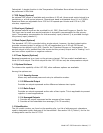
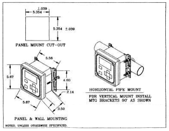
2.1 Mounting
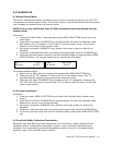
Three typical installation configurations are available for the LXT-230 transmitter: universal
mounting, handrail mounting, and panel mounting configurations. The universal mounting
configuration allows the LXT-230 to be mounted on a wall or a 2” pipe stand. U-bolts may
be ordered separately for pipe stand mounting.
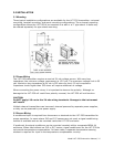
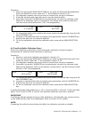
2.2 Power Wiring
The LXT-230 transmitter requires a nominal 24-vdc voltage source. With zero loop
impedance, the minimum voltage requirement is 13.5 vdc. The maximum voltage limit is 50
vdc. Maximum loop impedance at 24 vdc is 525 ohms for the 4-20 mA compliance.
Impedance levels higher than 525 ohms will require additional dc voltage.
When connecting the power wires, it is important to observe the polarity. Although no
damage to the LXT-230 will result from polarity reversal, the LXT-230 will not function.
CAUTION
Do NOT apply 110 vac to the 24-vdc wiring terminals. Damage to the instrument
will result!
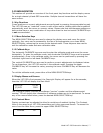
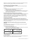
Multiple channel transmitters can have each channel powered by separate power supplies,
or they can be powered by one power supply.
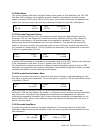
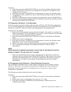
2.3 Sensor Wiring
A conditioned input is required from the sensor or electrode to the LXT-230 transmitter for
proper operation. In cases where S10 and S17 sensors are not used, a signal conditioning
module is available and can be mounted inside the LXT-230 enclosure.
If preferred, the signal conditioner can be mounted remotely within a separate NEMA 4X
enclosure. When used without an S10 or S17 sensor, signal conditioners for the LXT-230 do
not provide temperature compensation. In these cases, a separate temperature sensing
element is required for input to the temperature compensation circuitry.