


Model LXT-230 Instruction Manual / 10
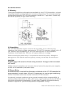
4.0 SENTINEL DIAGNOSTICS
The basic menu structure of the LXT-230 transmitter is architecturally the same as the LXT-
230 pH, ORP and PION, with the only variable being the diagnostic information on the main
and special diagnostic menus. The critical path to your process measurement is via the TAI
sensor/electrode.
Under perfect conditions, the electro-chemical interface between the electrode’s internal
reference cell (the measurement standard) and the liquid junction (bridge between the
internal electrolyte and the wet process) should be in balance (stable potential values).
However, a dominant failure mechanism of an Electro-Chemical (pH, ORP, PION)
Reference Half Cell is insidious process contamination impacting that balance (electrode
internal chemistry).
Contamination from the wet process will eventually migrate through the electrode’s inner
structure eventually changing Electro-Chemical balances via oxidation/reduction of the
metal/metal salts and gels.
4.1 Diagnostic set up and configuration menus
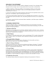
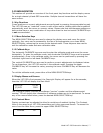
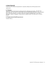
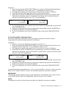
4.1.1 Main Menu
The degree to which the intrusive process chemicals degrades the “insitu” electrode is
graphically depicted on the right side of the LXT-230 main process screen as a vertically
expanding diagnostic bar, culminating in a flashing pre-pHault alert. This pre pHault Alert
warns the user of a pending chemical alteration of the Electro-Chemical Reference
Measurement Cell prior to the actual measurement error, hence the designation, “Pre-
pHault.”
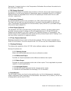
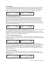
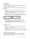
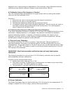
4.1.2 SENTINEL DIAGNOSTIC SCREEN
The lower section of this (split screen – over under) menu will indicate default mV values as
set by the factory; the default value will be 60mV in all cases. This value is Nurnstian in that
it signifies one decade change in 4 molar reference gel. The transmitter has been designed
so that the customer can input other mV values based on individual experience that may
differ from the default mV number.
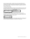
To change the “LIMIT” values, enter the CALIBRATE MODE by simultaneously pressing the
two horizontal CALIBRATE keys; observe the cursor move to the right allowing LIMIT value
change. Once in CAL MODE, the cursor can be moved to different digit placements, then,
using the vertical key, the LIMIT value can be decreased or increased based on process
demands.
NOTE:
This value responds to contamination of the secondary electrolyte chamber with a Nurnstian
response (log 10 System)
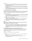
pH 7.00
_50.0% 25.0°C
Ref 25.2 mV
Limit 30.0 mV
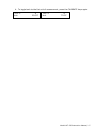
ORP 100.0 mV
25.0% 25.0°C