


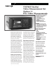
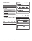
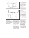
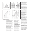

Frequency response measurements
M
ultiburst Flag Amplitude:
Measured from the center point
of the flag top to the ensuing
bottom of the flag. Result
e
xpressed as % of sampled bar
a
mplitude. See element C1 and
CCIR Recommendation 567.
M
ultiburst Amplitude (five
packets):
Measured as the
peak-to-peak amplitude of each
of the first five multiburst
p
ackets. The peak-to-peak
a
mplitude is measured over a
4.5 µsec window at the center
of the first two packets, and
over a 1.13 µsec window at the
center of the next three packets.
The last packet is not measured.
Results expressed as % of
sampled flag amplitude. See
elements C1 and C2 and CCIR
Recommendation 567.
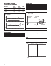
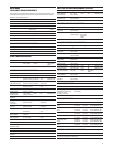
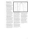
Linear waveform distortion
measurements
Baseline Distortion: Measured
as the difference between the
signal level 400 nanoseconds
after the half-amplitude point
of the trailing edge of the bar,
and the signal level at blanking
reference. The signal is first
band-limited to 3.3 MHz. Result
expressed as a % of sampled
bar amplitude. Sign is positive
if level nearest bar is highest.
See CCIR Recommendation 569
(paragraph 2.4) and Figure 1.
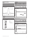
2T Pulse/Bar Ratio Error: Meas-
ured as the difference between
the sampled amplitude of the
2T pulse and the sampled bar
amplitude. The sign is positive
if the 2T pulse amplitude is
greater. Result expressed as a
% of sampled bar amplitude.
See elements B1 and B2 and
CCIR Recommendation 569.
Low frequency error
Low Frequency Error: Measured
as the peak-to-peak amplitude
of the most extreme sampled
fluctuations from black-level
that are in the frequency band
between 10 Hz and 2 kHz.
Expressed as a % of sampled bar.
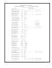
When ordering, please use the nomenclature given here. The standard instrument is shipped as a rack mount product.
Included Accessories
Instruction manual; 75 Ω terminators (3) 011-0102-00; power cord.
Options
Option 01 — NTSC Measurements
Option 01/11 — Dual Standard Measurements
Option 20 — Teletext Measurements
Option 21 — Camera Measurements
Option 30 — Component Measurements
Option 40 — Audio Measurement Module
Option 41 — 6 Channel Audio Measurement Module
Option 42 — Audio to Video Delay Measurement
Option 48 — GPIB Inter
face
Option 1C — Cabinet Version
Option 1G — Echo/Rounding Measurements
Option 1P — Printer
Option 1Z — Pr
obe Adapter (067-1429-00)
Option 3Z — Probe Adapter (3 each of 067-1429-00)
VM700T Software Utilities
VMBKUP — VM700T Backup Utility
VMREMGR — Remote Graphics Softwar
e for the VM700T
VMT — VM700T Remote Contr
ol Software
Optional Accessories
VM7FC1 — Field installable conversion kit to conver
t rackmount unit to cabinet.
VM7FR1 — Field installable conversion kit to conver
t cabinet to rackmount unit.
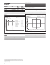
Ordering
Information
VM700T
Option 11
PAL Video
Measurement Set.
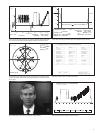
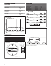
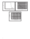
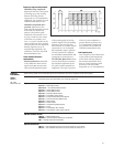
Elements C1 and C2 (CCIR Recommendation 569).
15