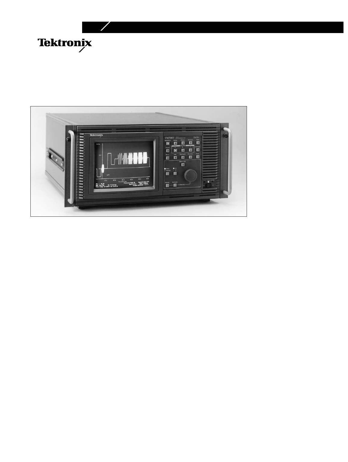
VM700T (turbo)
Video Measurement Set
Option 11
PAL Video Measurements
M
any capabilities in one instrument
–
Digitizing waveform monitor
– Digitizing vectorscope
– Picture Display
– Group delay and frequency
response
– Noise measurement set
– Automatic measurement set
Auto mode
– Unattended monitoring of PAL
video signals from studios, STLs,
Earth Stations, and transmitters
– User-specified limits
Measur
e mode provides graphic
display of measurements
– ICPM
– K factor
– Differential gain and phase
– Chrominance to luminance delay
– Noise spectrum
– Group delay with sin x/x
– Color bars
– Relative to reference on most
measurements
– Configurable for all standard
test signals
Award winning user interface
State-of-the-art architecture
Extremely fast update rate
Parallel and serial printer ports
Three input channels
Channel difference modes
External VGA display port
Fully documented r
emote control
operation
Har
dcopy for analysis and
documentation
Recognized with eight technical
Emmy awards and one Oscar for
outstanding contributions to the
television industry, Tektronix
world class core competencies
have enabled it to design and
deliver the most comprehensive
solutions in the industry.
The VM700T is a product of this
core competency. Recognized as
the defacto industry standard that
keeps pace with evolving cus-
tomer needs, the VM700T is a
total solution for your baseband
video and audio
1
monitoring and
measurement needs. Featur
es
such as an extremely fast and
fully automatic measurement
mode as well as full manual oper-
ation
pr
ovides the first time user
as well as the seasoned profes-
sional an unequaled value for their
test and measurement investment.
Automatic video measurement set
The VM700T Auto mode makes
standard video transmitter mea-
sur
ements quickly and automati
-
cally, including those specified
in CCIR Rep. 624-1, Rec. 567,
and Rec. 569. Both vertical inter-
val and full field measurements
can be made and compared with
user-defined limits. A dual limit
verification system is employed
to generate a caution or alarm
message when either limit is vio-
lated. Reports can be generated
and printed automatically at
operator scheduled times or trig-
gered from a conditional event.
Graphic displays of measurements
Measure mode provides virtual
real time graphic displays of
measurement results automati-
cally. Vertical interval or full
field measurements including
noise spectrum, group delay,
K-factor, dif
ferential gain and
differential phase are presented
as clever, easy to understand
interactive digital displays. Such
displays ar
e indispensable when
extremely fast measurement
update rates (up to 30 times a
second) are required to provide
instant feedback of critical
adjustments and analysis of
signal variations. User definable
limits are visually integrated into
each graphic display and can be
used to trigger a measur
ement
report or a user definable macro
function. Such a function can,
for example, dial out through a
Copyright © 1996, T
ektr
onix, Inc. All rights r
eser
ved.
1
Option 40 audio measurement package.


