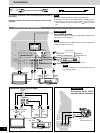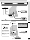
LOOP ANT
HOLDER
TV
VCR1 DVD
S-VIDEO
MONITOR
OUT
TV
TV
MONITOR CENTERSURROUND
COAXIALOPTICAL2
(DVD)
OPTICAL1
(TV)
VCR1
DVD/DVD 6CH
SUBWOOFER
OUT
IN IN
IN
(IN)(OUT)
PLAY
(IN)
REC
(OUT)
FRONT
IN
SUBWOOFER
L
R
R
L
R
L
GND
DIGITAL IN
FM
ANT
AM
ANT
75 Ω
GND
EXT
LOOP
RAL
FRONT
RBL
+
–
FRONT
R L
SURROUND
CENTER
+
–
AC IN
AC
OUTLET
SPEAKERS
CDPHONO TAPE
OUT
IN
321
2
3
1
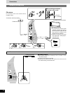
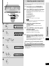
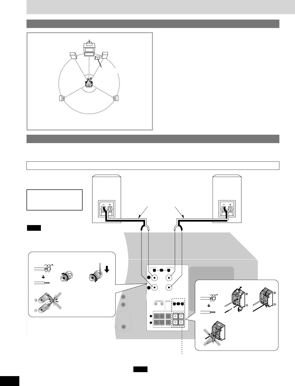
Speaker connections
10
RQT5802
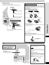
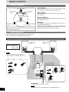
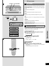
Placement of speakers
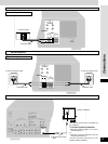
Connecting speakers
Front speakers
30° 30°
120°
b Front speaker
(left)
d Subwoofer
e Surround speaker
(left)
f Surround speaker
(right)
a Center speaker
c Front speaker
(right)
Front speakers
Place on the left and right of the TV at seated ear height so that
there is good coherency between the picture and sound.
Center speaker
Place underneath or above the center of the TV. Aim the speaker at
the seating area.
Surround speakers
Place on the side of or slightly behind the seating area, about one
meter higher than ear level.
Subwoofer
The subwoofer can be placed in any position as long as it is at a
reasonable distance from the TV.
Note that some experimentation can yield the smoothest low
frequency performance. Placement near a corner can increase the
apparent output level, but can result in unnatural bass.
Other connections are possible depending on your speaker system.
See your speaker system’s operating instructions for details.
g Front speaker
(right)
If you connect speakers with an impedance
under 6 Ω, switch on “LOW IMP” (
\
page 14).
Note
i Speaker cables
h Front speaker
(left)
Speaker impedance:
A or B: 4-16 Ω
A and B: 8-16 Ω
“B” terminals
For connection to a second pair of speakers.
Use the A terminals to enjoy SURROUND, SFC and DVD 6CH INPUT.
Note
The front, center, and surround speakers should be placed at
approximately the same distance from the seating area. The angles
in the diagram are approximate.


