


10
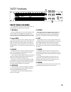
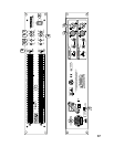
REAR PANEL FEATURES
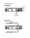
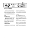
9. Line Cord Socket and Fuse
Here is where you connect the detachable line
cord that came in the box with your T•231. Plug
the other end of the line cord into an AC outlet
properly confi gured with the voltage required for your
particular model (see AC Select Switch next).
The fuse is located behind the fuse cover, at the
bottom of the IEC socket. See the “Troubleshooting”
section on page 12 for information about replacing
the fuse.
10. AC Select Switch
Set this switch to the correct voltage setting for the
country you are in, 115 VAC or 230 VAC.
Note: The T•231 is shipped with the AC Select
switch set to the 230 VAC position. If you are in a
country that uses 100-120 VAC, remove the cover
plate with a phillips-head screwdriver and set the
switch to the 115 VAC position. A 315 mA fuse
is used for both voltages (115V/230V). See the
“Troubleshooting” section on page 12 for instructions
on replacing the fuse.
11. GND LIFT Switch
When the switch is in the GND position, the audio
ground is electrically connected to the chassis
“safety” ground. Normally, this is how the switch is set.
However, occasionally a ground loop can be
created in a system where the signal ground is
connected to chassis ground, which can cause a
hum or buzz to appear in the audio signal. If this is
the case, try moving the switch to the LIFT position to
eliminate the hum or buzz.
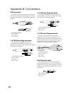
12. OUTPUTS
Three types of connectors are provided for the
outputs — balanced male XLR and 1/4” TRS (Tip-
Ring-Sleeve), and unbalanced RCA. These balanced
outputs are in parallel, and provide exactly the same
signal on all three outputs, regardless of which input
jack is used. You can connect either a balanced TRS
connector or an unbalanced TS connector to the 1/4”
output jack.
13. INPUTS
Three types of connectors are provided for the
inputs — balanced female XLR and 1/4” TRS (Tip-Ring-
Sleeve), and unbalanced RCA. These inputs are in
parallel, so do not connect more than one signal at
a time to the input jacks for each channel.
You can
connect either a balanced or an unbalanced
signal to
the 1/4” input jack.
See “Appendix B: Connections” on page 14 for
information on input and output connection wiring.
WARNING: TO REDUCE THE RISK OF FIRE OR ELECTRIC SHOCK,
DO NOT EXPOSE THIS EQUIPMENT TO RAIN OR MOISTURE. DO NOT REMOVE COVER.
NO USER SERVICEABLE PARTS INSIDE. REFER SERVICING TO QUALIFIED PERSONNEL.
AVIS : RISQUE DE CHOC ELECTRIQUE — NE PAS OUVRIR
RISK OF ELECTRIC SHOCK
DO NOT OPEN
UNBAL BALBAL/UNBAL
BAL/UNBAL
BAL
OUT
IN
GND
LIFT
315mA 250V
T
SERIAL / DATE CODE
OUT
IN
OUT
IN
OUT
IN
UNBAL BAL BAL
OUT
IN
OUT
IN
CHANNEL 1
CHANNEL 2
RISK OF FIRE
REPLACE FUSE AS MARKED
WARNING
NO
OUTDOOR
USE
B
R
O
U
G
H
T
T
O
Y
O
U
B
Y
T
H
E
G
R
O
O
V
Y
F
O
L
K
S
I
N
W
O
O
D
I
N
V
I
L
L
E
,
W
A
,
U
S
A
M
A
N
U
F
A
C
T
U
R
E
D
I
N
C
H
I
N
A
•
F
A
B
R
I
Q
U
E
A
U
C
H
I
N
E
"
T
A
P
C
O
"
A
N
D
"
M
A
C
K
I
E
"
A
R
E
R
E
G
I
S
T
E
R
E
D
T
R
A
D
E
M
A
R
K
S
O
F
L
O
U
D
T
E
C
H
N
O
L
O
G
I
E
S
I
N
C
.
• C
O
P
Y
R
I
G
H
T
©2
0
0
3
WWW.TAPCOGEAR.C
OM
A
C
1
0
0
-
1
2
0
V
,
6
0
H
z
A
C
2
0
0
-
2
4
0
V
,
5
0
H
Z
R
A
T
E
D
I
N
P
U
T
:
1
2
.
5
W
115V
9
10
11
12
13