9
12.0 TECHNICAL SPECIFICATIONS AND DRAWINGS
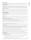
PERFORMANCE
Maximum Output Power
(1) (2)
Minimum Nominal
Load Impedance
Distortion
Minimum Frequency Bandwidth
Input Impedance
Current Draw at 4 Ω
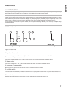
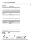
FRONT PANEL
Level Control
Crossover Frequency Adjustment
Phase Control
Crossover/Bypass Switch
On/Auto Switch
Power On Indicator
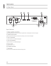
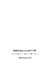
REAR PANEL
Input Connectors
Link Connectors
Output Connectors
Mains Voltage Connector
Mains Voltage Fuse Holder
REAR PANEL SWITCHES
Power Switch
Limiter Function
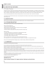
DIMENSIONS
Net Dimensions
(HxWxD)
Shipping Dimensions (HxWxD)
WEIGHT
Net Weight (each) - kgs (lbs)
Shipping Weight (each) - kgs (lbs)
APPROVALS
CSA C/US & FCC
iwSA 500 SUBWOOFER AMPLIFIER
500
Watts Continuous into 4 Ω
250 Watts Continuous into 8 Ω
4 Ω
<1% @ Maximum Rated Output
20Hz - 500Hz (no filters or EQ)
>20 kΩ
5 Amps
Adjusts Input Signal Level
50Hz - 150Hz
0° - 180° Continuously Variable
Engages or Disengages Low Pass Filter
On Continuous / Sleep Mode
Blue LED
2 x RCA
2 x RCA
4 x Gold Plated Binding Postings
120 Volt IEC - 2 Conductor
T5AL, 250 Volt
Switchable 1 Sub or 2 Sub (See Page 9.)
99 x 483 x 372 (3
7
/8 x 19 x 14
5
/8)
208 x 538 x 445 (8
3
/16 x 21
3
/16 x 17
1
/2)
6.8 (15)
8.6 (19)
PHASE
POW ER
CROSSOVER
ON
AUTO
CROSSOVER
FREQUENCY
LEVEL
BY PASS
50 150 0 180
OUTPUT 1
1 SUB
2 SUBS
LINE IN LINE OUT
OFF ON
5A 120V~60HZ
T5AL 250V
LIMITER
FUNCTION
CAUTION:
FOR CONTINUED PROTECTION
AGAINST RISK OF FIRE, REPLA
CE
ONLY WITH SAME TYPE FUSE AND RA
TIN
G
.
ATTENTION:
UTILISER UN FUSIBLE DE RECHANGE
DE MEME TYPE ET CALIBRE.
OUTPUT 2
+ +
+
iwSA 500
incl. Feet & Rack Ears
NOTES
(1) Thermal protection may occur at high continuous power.
(2) Depending on configuration, output power may be lower due to limiting circuit.
CAUTION
RISK OF ELECTRIC SHOCK
DO NOT OPEN
ATTENTION
RISQUE DE CHOC ELECTRIQUE
NE PAS OUVRIR
427
(16
7
/
8
)
90
(3
1
/
2
)


