


DEFINITION DC10A OWNER’S MANUAL_05
MASS LOADING
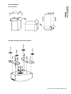
These loudspeakers are designed to be mass loaded, if wished, to lower the centre of gravity and improve stability,
resulting in improved sound quality. To do so, remove the 4 screws securing the access plate to the bottom of the
loudspeaker. The loading volume can be lled with sand (which must be dry), or propriety materials available for such
purposes from your retailer. Feel free to experiment with the volume of loading material used, to achieve optimum bass
performance and stereo imaging. (See g. 2)
FITTING PLINTHS & FLOOR SPIKES
Attach the two plinth sections using the screws and hex tool provided. These loudspeakers are designed to perform best
with the carpet piercing spikes tted, for optimum stability. These are supplied, along with locking wheels, and should be
inserted into the threaded holes in the base of the cabinet. Level the speaker, using the hex tool and then tighten the locking
wheels rmly but without using undue force. Spike locating cups are provided in the accessory pack and these may be used
to protect sensitive oor surfaces. (Shown also in g. 2)
Warning:
Ensure that the spikes are levelled and that the lock nuts are tightened rmly. The spikes should be pushed through the
carpet to locate into the ooring surface by applying pressure to the top of the cabinet. Failure to do so could render the
speaker unsteady and result in damage or injury should it be knocked over.
INSTALLATION
To avoid potential damage to your loudspeaker, ensure that the amplier is switched OFF prior to connecting or
disconnecting any cables. Before switching on double check that all connections are secure and that polarity is correct.
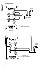
CONNECTION IN SINGLE WIRE MODE
Using the supplied link cables, connect the high frequency (HF) and low frequency (LF) terminals respectively, as shown.
These must be removed to Bi-wire the speakers - see section entitled Connection in Bi-wire Mode. For optimum
performance in single wire mode, loudspeaker cable connections from the amplier should be made to the high frequency
(HF) terminals of the loudspeaker: (See g. 3)
• The positive (plus) terminal on the amplier left channel (marked + or coloured red) must be connected to the positive
HF terminal on the left speaker. The left speaker is the one on the left as you look at the stereo pair from your listening
position.
• The negative (minus) terminal on the amplier left channel (marked - or coloured black) must be connected to the negative
HF terminal on the left speaker.
• Repeat this connection process for the right speaker. Remember that the positive (+ or red) on the amplier must be
connected to the positive (+ or red) on the speaker and the negative (- or black) to negative.
• Select a signal source, such as a CD player; switch on the amplier and slowly turn up the volume control to
check that both loudspeakers are reproducing bass and treble information.
11
12
13
14
15
16
17
18
19
20