


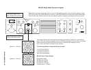

10 • SM-900 USER GUIDE
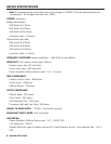
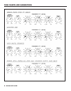
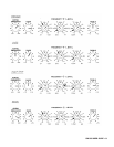
TONE CHARTS AND SUGGESTIONS
The following two pages include suggested settings to get you acquainted with the limitless vari-
ety of tones possible with the SM-900. By setting EQ 1 to the “Acoustic 360” and EQ 2 to the
“Grand Piano” settings, for example, you can switch back and forth with the footswitch and see
the variety of diverse sounds available to you on the SM-900.
CROSSOVER FREQUENCY
This function sets the crossover point or dividing point of the sound spectrum and sends the lower
notes to the LOW output jack on the back panel and the higher, treble notes to the HI output jack
on the back panel. For example, if the Frequency is set at mid-position or 500Hz, all frequencies
BELOW 500 Hz will appear at the LOW output jack. All frequencies ABOVE 500Hz will be present
at the HI output jack.
If you are still confused on how to set the crossover point, you can refer to the owners manual
that came with your speakers. It will probably recommend a crossover point. Another reference,
which is probably the best, is your own ears. Once you have set up your system, rotate the
Crossover Frequency control until the sound seems balanced or, simply, sounds the best.
The crossover slope is 12 dB per octave.
Note: Nearly all of SWR’s speaker systems are desinged to be run FULL RANGE and bi-amping
is not recommended for all situations. Bi-amping causes a natural “suck out” at the crossover
point and some phase problems can occur.
BALANCE
The Balance control works only when biamping (refer to page 19). The Balance control sets the lev-
els of the highs and lows with respect to each other. Since this circuit is passive, rotating the
Balance control towards the low position cuts the highs. Likewise, rotating the control towards the
hi position cuts the lows. Therefore, if you need more lows and less highs, rotate the control
counter-clockwise from mid-position. If you need more highs and less lows, rotate the control clock-
wise from mid-position.
LIMITER
The Limiter control is actually a Threshold adjustment for the Limiter circuit. In the fully counter-
clockwise position, the limiter circuit is disengaged. As you rotate the control clockwise, the
threshold (point at which the Limiter circuit is engaged) is lowered. The LED to the right of this
control will light when the limiter is working. The farther the control is rotated, the more drastic
the limiting becomes and a “fatter” sound is achieved.
The Limiter circuit in the SM-900 adds NO noise and very little distortion. You should also notice
that there is little “pumping” or “drop off” as experienced in lesser-quality units. The design of the
limiter circuit has what is known as a “soft knee.” This essentially means that you can get a com-
pression effect as the limiter threshold is just engaged.
The Limiter circuit is driven by the Gain control and the amount of cut and boost in the tone sec-
tion. If you desire more limiting than is achievable with the Limiter control at maximum, turn up
the Gain control (but keep an eye on the preamp clip LED).
We put the Limiter circuit just before the Effects Loop. If, on some of the peaks, you are overdriv-
ing your effects, you can correct the problem using the Limiter. Any undesired loss in volume
caused by the Limiter can be made up by raising the Master Volume.
EFFECTS BLEND
This function blends the signal from your instrument with that coming from your effects unit. With
the Effects Blend fully counter-clockwise (“dry”), no signal from your effect will be heard. As you