


ASSEMBLY
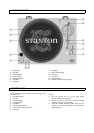
1. Remove the main unit with the packing from the box
and take off the packing.
2. Insert the turntable platter onto the center spindle.
3. Set the slip mat on the platter.
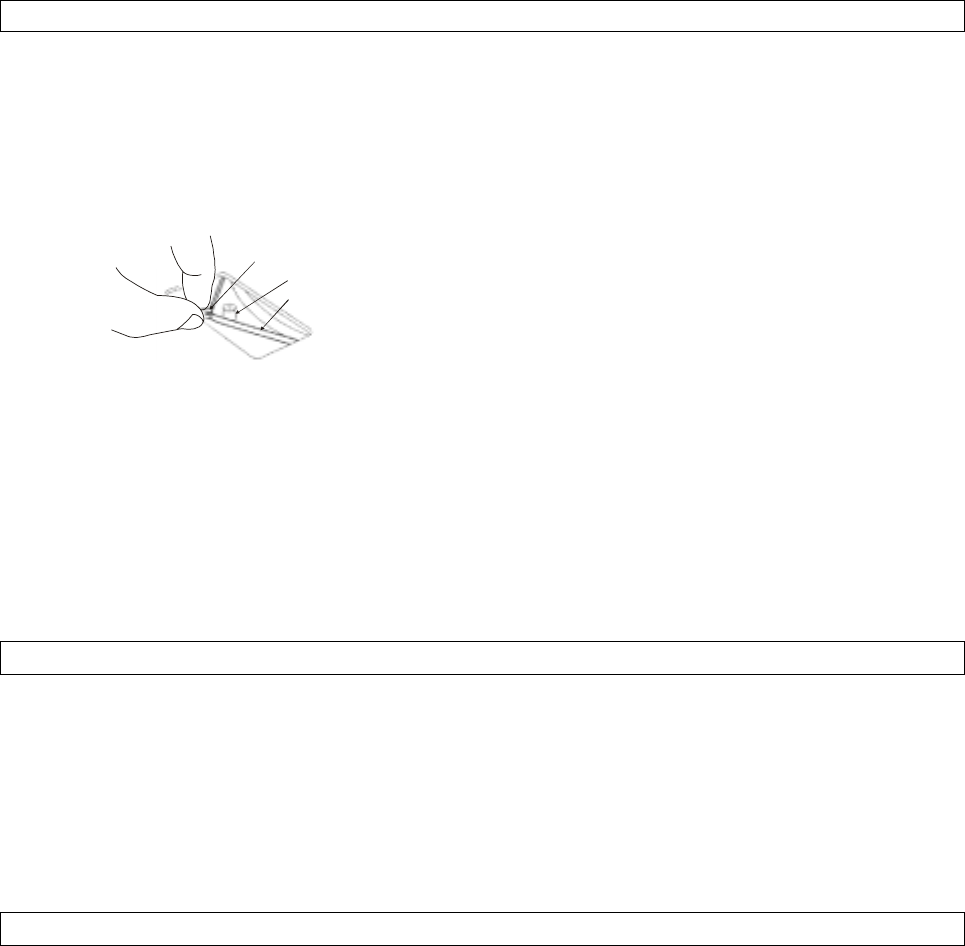
4. Hold the ribbon tape which is attached to the belt
and loop the belt over the motor pulley. Be sure it
does not twist.
Ribbon tape
Driving roller
Drive belt
5. Insert the headshell into the front end of the
tonearm, then turn the lock nut clockwise with the
headshell firmly held horizontally.
6. Slide counterweight onto tonearm.
Twist it lightly and it will screw onto the rear shaft
of the tonearm.
7. Adjustment of horizontal zero (0) balance and
stylus pressure:
(a) Remove the stylus protector, do not touch the
stylus tip during the adjustment.
(d) Release the arm clamp and lift the tonearm
from the arm rest to free it.
(c) Rotate the counterweight until the tonearm is
approximately balanced horizontally (floats
freely).
(d) Refasten the tonearm with the arm clamp.
(e) Hold the counterweight stationary with one
hand and rotate only the stylus-pressure ring
to bring the number "0" of the ring into
alignment with the center line on the tonearm
rear shaft.
(f) Rotate the counterweight clockwise until the
scale shows the value corresponding to the
pressure of the used stylus. The average stylus
pressure of the cartridge body is 2g. If you use
a non-Stanton cartridge, please follow that
manufacturer’s instructions.
8. Install the dust cover to the main unit.
PLACEMENT
• Do not place the unit in a location where it will be
exposed to direct sunlight or near a heating appliance.
• Do not place the unit in a location where there is high
humidity or a lot of dust.
• Cartridge may pick up slight sound pressures or
vibrations from the speakers coming along the floor
or through the air resulting in feedback. Find a
location which is very stable and vibration free.
• The legs have functions for adjusting the height of
the unit itself. Adjust the legs to stabilize the main
body horizontally.
CONNECTIONS
1. Connect the power cord to the auxiliary power outlet
on the rear panel of your amplifier or receiver or to a
household AC outlet.
2. Connect the unit output terminals to the PHONO
jack of your amplifier or receiver.
Output terminals Amplifier(Receiver)
L (White) >> L Channel
R (Red) >> R Channel
GND (Spade) >> GND
NOTE:
Be sure to connect the ground terminal firmly to the
amplifier or receiver.
If this connection is not made or is loose, a power
source "HUM" will result.