


5
1. Checking the Contents
Check that the carton contains the following items:
1) Main unit
2) Control unit
3) Operating instructions (this booklet)
4) Two pair of RCA pin cord.
5) Control cords (1 meter)
6) Power cord
7) Two fader start cables
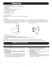
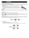
2. Installing the Unit
Mount the unit onto your console or rack with 19" EIA rack
rails.
CAUTION:
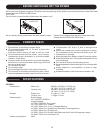
The player will work normally when the main unit is
mounted with the front panel at within 15 degrees of the
vertical plane. If the unit is tilted excessively, discs may
not be loaded or unloaded properly.
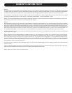
The control panel's LCDs are designed to be
clearly visible within the angles shown in Figure 2.
Mount the control unit so that the visual angle is
within this range.
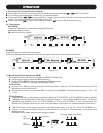
Connections
1) Turn off the POWER switch.
2) Connect the RCA pin cord to the input on your mixer.
3) Connect the control cords to the REMOTE connector on the main unit.
CAUTION:
Be sure to use the supplied control cords. Using another type of cable may result in damage.
Be sure the power is off when connecting the control cords. Otherwise the units may not work properly.
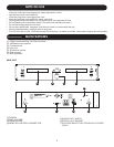
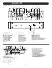
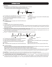
(1) POWER (Power ON/OFF Switch)
When the POWER switch is pressed , the power
turns on.
(2) DISC HOLDER
Place the discs in the holder . Press the OPEN/
CLOSE button to open and close the disc holder.
(3) OPEN/CLOSE
Press it to open and close the disc holder . The
control unit also includes OPEN/CLOSE button.
The disc holder cannot be opened during playback,
so stop playback before pressing the button.
(4) REMOTE CONTROL CONNECTOR
(5) AUDIO OUT
(6) DIGITAL OUT SOCKET
Connect this connector to the control unit using
the included control cord.
The audio signals from each player are output
from these jacks.
The music signal of this socket is digital. Connect
the output to the respective digital input of a digital
amplifier for example.
Main Unit Front Panel
Main unit
Figure1 Figure2
Control
Panel Button
Max
15
45
5
NAMES AND FUNCTIONS
1. Handle the power supply cord carefully
Do not damage or deform the power supply cord.
If it is damaged or deformed, it may cause electric
shock or malfunction when used. When removing
from wall outlet,be sure to remove by holding the
plug attachment and not by pulling the cord.
2. In order to prevent electric shock, do not open the
top cover. If a problem occurs, contact your dealer.
3. Do not place metal objects or spill liquid inside the
CD player. Electric shock or malfunction may result.
WARNING:
TO PREVENT FIRE OR SHOCK HAZARD, DO NOT
EXPOSE THIS APPLIANCE TO RAIN OR MOISTURE.
TO PREVENT ELECTRIC SHOCK DO NOT USE
THIS (POLARIZED) PLUG WITH AN EXTENSION
CORD, RECEPTACLE OR OTHER OUTLET UNLESS
THE BLADES CAN BE FULLY INSERTED TO
PREVENT BLADE EXPOSURE.
IMPORTANT TO SAFETY
NOTE:
This CD player uses the semiconductor laser. To allow
you to enjoy music at a stable operation, it is recommended
to use this in a room of 5ºC 41ºF - 35ºC 95ºF.
CAUTION:
Please, record and retain the Model name and serial
number of your set shown on the rating label.
Model No. ___________ Serial No. ___________
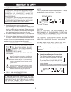
CAUTION: TO REDUCE THE
RISK OF ELECTRICf SHOCK,
DO NOT REMOVE THE COVER
(OR BACK) . THERE ARE NO
SERVICEABLE PARTS INSIDE.
The lightning flash with arrowhead symbol,
within an equilateral triangle, is intended to
insulated "dangerous voltage" within the
product's enclosure that may be of sufficient
magnitude to constitute a risk of electric
shock to persons.
The exclamation point within an equilateral
triangle is intended to alert the user to the
presence of important operating and
maintenance (servicing) instructions in the
literature accompanying the appliance.
REFER SERVICING TO QUALIFIED SERVICE
PERSONNEL.
FOR U.S.A. & CANADA MODEL ONLY
CAUTION
CAUTION:
USE OF CONTROLS OR ADJUSTMENTS OR
REFORMANCE OF PROCEDURES OTHER THAN
THOSE SPECIFIED HEREIN MAY RESULT IN
HAZARDOUS RADIATION EXPOSURE.
THE COMPACT DISC PLAYER SHOULD NOT BE
ADJUSTED OR REPAIRED BY ANYONE EXCEPT
PROPERLY QUALIFIED SERVICE PERSONNEL.
DOUBLE INSULATED - WHEN SERVICING, USE
ONLY IDENTICAL REPLACEMENT PARTS.
NOTE:
This unit may cause interference to radio and television
reception.
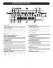
Line Voltage Selection (for multiple voltage
model only)
The desired voltage may be set with the
VOLTAGE SELECTOR switch on the rear
panel, using a screwdriver.
Do not twist the VOLTAGE SELECTOR
switch with excessive force as this may
cause damage
If the VOLTAGE SELECTOR switch does not move
smoothly, please contact a qualified serviceman.
1
RATING LABEL
CLASS 1 LABEL
115V
230V