


Page F-7
X-Rack Master Module
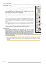
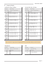
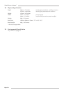
F.7 Connector Details
Ins Snd, Mix, Rec, Fol Mon
Location: Rear Panel
Conn’ Type: 25-pin ‘D’ Type Female
Pin Description Cct
1 Follow Monitor Right (+ve)
814 Follow Monitor Right (–ve)
2 0V
15 Follow Monitor Left (+ve)
73 Follow Monitor Left (–ve)
16 0V
4 Record Output Right (+ve)
617 Record Output Right (–ve)
5 0V
18 Record Output Left (+ve)
56 Record Output Left (–ve)
19 0V
7 Mix Output Right (+ve)
420 Mix Output Right (–ve)
8 0V
21 Mix Output Left (+ve)
39 Mix Output Left (–ve)
22 0V
10 Mix Insert Send Right (+ve)
223 Mix Insert Send Right (–ve)
11 0V
24 Mix Insert Send Left (+ve)
112 Mix Insert Send Left (–ve)
25 0V
13 n/c
Ins Rtn, Ext, Mon, Alt Mon
Location: Rear Panel
Conn’ Type: 25-pin ‘D’ Type Female
Pin Description Cct
1 Alt Monitor Out Right (+ve)
814 Alt Monitor Out Right (–ve)
2 0V
15 Alt Monitor Out Left (+ve)
73 Alt Monitor Out Left (–ve)
16 0V
4 Main Monitor Out Right (+ve)
617 Main Monitor Out Right (–ve)
5 0V
18 Main Monitor Out Left (+ve)
56 Main Monitor Out Left (–ve)
19 0V
7 External Input Right (+ve)
420 External Input Right (–ve)
8 0V
21 External Input Left (+ve)
39 External Input Left (–ve)
22 0V
10 Mix Insert Return Right (+ve)
223 Mix Insert Return Right (–ve)
11 0V
24 Mix Insert Return Left (+ve)
112 Mix Insert Return Left (–ve)
25 0V
13 n/c
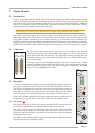
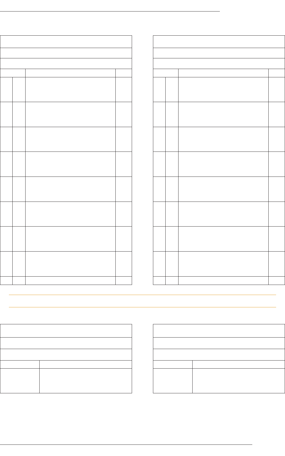
Headphones
Location: Front Panel
Conn’ Type: Stereo 1/4" Jack Socket
Pin Description
Tip Left
Ring
Sleeve 0V
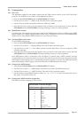
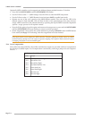
PL2
Location: Internal
Conn’ Type: 16-pin IDC Plug
Pin Description
n/a For Future Expansion
Please note that the ‘D’ type connector binding posts fitted to the X-Rack Master Module are 4-40 UNC thread.