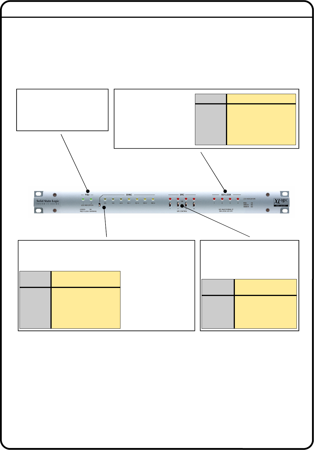
Front Panel Description
Sync Source Selection
Sync Source SelectionSync Source Selection
Sync Source Selection
A 3-position toggle switch for selecting the audio sync source. The switch’s ‘down’
position is latching, while its ‘up’ position is momentary. Repeated ‘upward’
presses on the switch scroll through the possible external sync sources. The
adjacent amber LEDs indicate the
currently-selected source.
When the LED for the desired
source is on, the switch may be
placed in the latching ‘down’
position to prevent inadvertent
further changes of sync source.
Switch
Position
Function
Centre No Action
Up
(Momentary)
Increments Sync Source
Selection
Down
(Latches)
Locks Sync To Chosen Source
SRC Control
SRC Control SRC Control
SRC Control
Four 2-position toggle switches controlling
the four 16-channel output SRCs. The switch
also enables external GPI control of each
SRC.
PSU Status
PSU StatusPSU Status
PSU Status
Two bi-colour LEDs confirming the current
status of each PSU. The LEDs are green in
normal operation and flash red if a PSU
fault condition is detected.
SDI Lock LEDs
SDI Lock LEDsSDI Lock LEDs
SDI Lock LEDs
Four tri-colour LEDs, for SDI inputs 1
to 4. Each illuminates when a valid
SDI video signal is detected at its
input, and the colour indicates the
interface standard in use.
Colour SDI Format
Yellow SD-SDI
Green HD-SDI
Red 3G-SDI
Off No Valid SDI Signal Detected
Switch
Position
Function
Up SRC On
Down
SRC Off, but under external
GPI control
8
88
8


