


12
1212
12
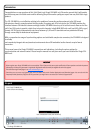
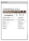
Installation
MADI Outputs
MADI OutputsMADI Outputs
MADI Outputs
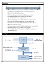
The 64 de-embedded audio channels are also available as MADI (Multichannel Audio Digital Interface), in both co-axial and optical formats.
The MADI bit stream contains all 16 channels from all four SDI inputs. The channel numbering within the MADI bit stream is one-to-one, i.e.,
Channel 1 of SDI 1 becomes MADI Channel 1, Channel 2 of SDI 1 becomes MADI Channel 2, and so on for the remainder of SDI 1’s audio
channels. Then Channel 1 of SDI 2 becomes MADI Channel 17, and the cycle repeats. If less than four SDI inputs are in use, the
MADI bit stream time slots corresponding to the unused inputs will simply contain all zeroes.
The co-axial MADI output is on a BNC socket, and is compliant with AES10id-
2008. The characteristic impedance is 75
Ω
, at a nominal data rate of 125Mbps.
Transmission distances up to 50 m are generally achievable.
The same bit stream is available in optical format on an ST type connector,
allowing the MADI output signal to be transmitted by fibre if preferred.
Recommended fibre types are 62.5/125 µm or 50/125 µm, multimode.
Transmission distances of at least 1000 m are achievable.
Redundant MADI connection
Redundant MADI connectionRedundant MADI connection
Redundant MADI connection
Using an SSL MADI Opti
SSL MADI OptiSSL MADI Opti
SSL MADI Opti-
--
-Coax
Coax Coax
Coax unit the copper coaxial MADI signal can be converted to a parallel optical signal for a redundant optical
connection (or vice versa for a redundant copper connection)
RS
RSRS
RS-
--
-422 Port
422 Port422 Port
422 Port
The rear panel includes an RS-422 port on a 9-pin female Dsub connector. This connector has no function at this time.
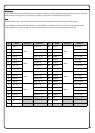
SDI Input MADI Channels
SDI 1 1 to 16
SDI 2 17 to 32
SDI 3 33 to 48
SDI 4 49 to 64
GPIO Port
GPIO PortGPIO Port
GPIO Port
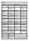
A GPIO (General-Purpose Input-Output) port is available at the rear panel in the form of a 9-pin female Dsub connector. This has four inputs and
four outputs, and allows the SDI-MADI’s four output SRCs (Sample Rate Converters) to be enabled from external control equipment by contact
closure. Tallies confirming the SRC status are also available on this connector.
Pinout is as follows:
GPIO Port Pin Function
1 GPI 1
2 GPI 2
3 GPI 3
4 GPI 4
5 Ground
6 Talley 1
7 Talley 2
8 Talley 3
9 Talley 4
ETHERNET Port
ETHERNET PortETHERNET Port
ETHERNET Port
The XLogic SDI-MADI includes a standard Ethernet port (an RJ45 socket). This connector has no function at this time.
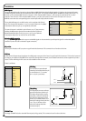
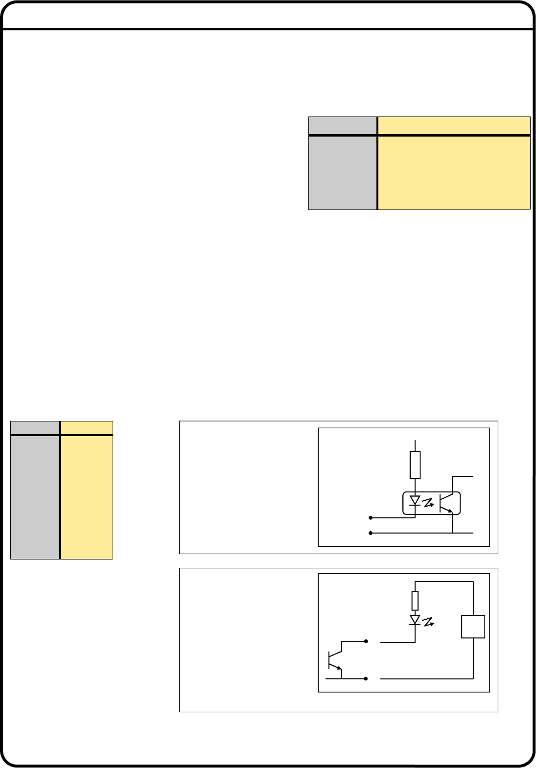
GPI Wiring
GPI WiringGPI Wiring
GPI Wiring
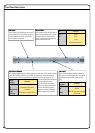
The GPI inputs are opto-isolated
internally, and activate when the pin
is connected to 0 V. (i.e. connect
pins 1-4 to pin 5 to activate).
Vcc
Pin 1*
Pin 5
* Pins 2-4 are identical
Talley Wiring
Talley WiringTalley Wiring
Talley Wiring
The tally outputs are open-collector
type, with transistors rated to 24 V.
The tallies will typically be used to
drive LEDs; connect the cathode of
the LED to the tally output and the
anode, via a suitable resistor, to an
external DC voltage of not more than
+24 V. The 0 V reference of the
external DC voltage should be
connected to pin 5.
LED
Pin 5
* Pins 7-9 are identical
0V
Pin 6*
Ext
PSU