


46
Appendix D:
Program Examples
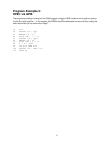
All of the program examples which follow do the
same thing, only the computer, language, or
interface is changed. The programs read the
Channel 1 and 2 Outputs and write the results to
the computer screen. In addition, the X6 analog
output port is ramped from 0 to 10V.
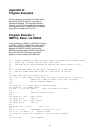
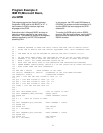
Program Example 1:
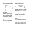
IBM PC, Basic, via RS232
In this example, the IBM PC's ASYNC port (known
as COM1: or AUX: to DOS users) will be used to
communicate with the SR530. Only two wires
between the IBM PC's ASYNC port and the
SR530 are needed (pins #2 & #3 of the RS232),
but pins 5,6,8 and 20 should be connected
together on the connector at the IBM end.
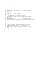
10 ′ EXAMPLE PROGRAM TO READ THE SR510 OUTPUT AND RAMP THE X6 ANALOG OUTPUT
20 ′ USING IBM PC BASICA AND THE COM1: RS232 PORT.
30 ′ THE RAMP ON X6 CAN BE WATCHED BY SETTING THE SR530 DISPLAY TO A/D.
40 ′
50 ′
60 ′ ON THE REAR PANEL OF THE SR530, SET SWITCH #1 OF SW2 DOWN
70 ′ AND ALL OTHER SWITCHES IN SW2 UP. (9600 BAUD, NO PARITY)
80 ′
90 OPEN ″COM1:9600,N,8,2,CS,DS,CD″ AS #1
100 ′ SET UP COM1: PORT TO 9600 BAUD, NO PARITY, 8 DATA BITS, 2 STOP BITS,
110 ′ IGNORE CTS (CLEAR TO SEND), DSR (DATA SET READY),
120 ′ AND CD (CARRIER DETECT).
130 ′
140 PRINT #1, ″ ″ ‘CLEAR UART BY SENDING SPACES
150 PRINT #1, ″Z″′RESET SR530
160 FOR I = 1 TO 200: NEXT I ′WAIT FOR RESET TO FINISH
170 ′
180 X = 0 ′INIT X6 OUTPUT TO ZERO
190 ′
200 PRINT #1, ″Q1″ ′READ OUTPUT
210 INPUT #1,V1 ′INTO V1
220 PRINT #1, ″Q2″′READ OUTPUT
230 INPUT #1,V2 ′INTO V2
240 ′
250 PRINT ″CH1 = ″;V1;″ CH2 = ″;V2
260 ′
270 X =X + .0025 ′INCREMENT X6 OUTPUT BY 2.5 MV
280 IF X > 10 THEN X = 0 ′RESET X6 RAMP
290 PRINT #1, USING ″X6, ##.###″;X ′SET X6 OUTPUT VOLTAGE
300 ′
310 GOTO 200 ′LOOP FOREVER