


37
or, generates the gate pulse during which reference
pulses are counted.
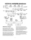
I/O addresses are decoded by U705, U706, and
U707. The microprocessor controls the lock-in
functions through I/O ports U714-U721. U713
generates an interrupt to the CPU every 4 msec to
keep the microprocessor executing in real time.
RS232 Interface
The RS232 interface uses an 8251A UART, U801,
to send and receive bytes in a bit serial fashion. Any
standard baud rate from 300 to 19.2K baud may be
selected with the configuration switches. The X16
transmit and receive clock comes from counter 2 of
U704. The RS232 interface is configured as DCE so
that a terminal may be connected with a standard
cable. When a data byte is received by the UART,
the RxRDY output interrupts the CPU to prevent the
data from being overwritten.
GPIB Interface
The interface to the GPIB is provided by U802, an
MC68488 General Purpose Interface Adapter
(GPIA). The GPIB data and control lines are
buffered by drivers U808 and U811. Because the
GPIA uses a 1 MHz clock, wait states are provided
by U805 to synchronize I/O transactions with the 4
MHz CPU. The GPIA interrupts the CPU whenever
a GPIB transaction occurs which requires the CPU’s
response. (The GPIB address is set by switch bank
SW1.)
Power Supplies
The line transformer provides two outputs, 40VAC
and 15VAC, both center tapped. The transformer
has dual primaries which may be selected by the
voltage selector card in the fuse holder. The 15VAC
is rectified by diode bridge BR2 and passed to 5V
regulator U909. The output of U909 powers the
microprocessor and its related circuitry. The 40VAC
output is half-wave rectified by BR1 and regulated by
U901 and U902 to provide +20V and -20V. These
two dc voltages are then regulated again by 15V
regulators U903-U908. Each 15V regulator powers
a separate section of the lock-in to reduce coherent
pick up between sections. U911 and U912 provide
plus and minus 7.5V and U910 generates +5V for
the analog circuits.
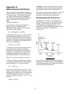
Internal Oscillator
The internal oscillator is on a small circuit board
attached to the rear panel of the instrument.
Local regulators, Q1 and Q2, provide power to
the board. The VCO input is internally pulled up
by R12. This pulls the VCO input to 10V when
the VCO input is left open. 2/4 U1 translates the
VCO input voltage to provide a negative control
voltage to U2, the function generator. P3
adjusts the VCO calibration. U2 is a sine wave
generator whose frequency range is selected by
the VCO Range switch and capacitors, C4-C6.
P2 adjusts the sine wave symmetry at low
frequencies. 4/4 U1 buffers the output of U2.
P1 adjusts the amplitude of the output sine
wave. The output amplitude on the SIne Out is
selected by the amplitude switch. The output
impedance is 600 Ω.