


(Continued
from
page
7
1)
INTERNAL
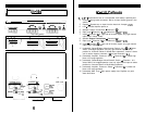
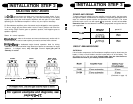
The Soundstream amplifiers are fused internally with automotive-type fuses.
The fuses are accessible via a plastic plug on the bottom of the amplifier. Never
replace the fuses with a higher value than what is supplied.
This may
result in amplifier damage and will void the
warranty!
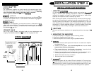
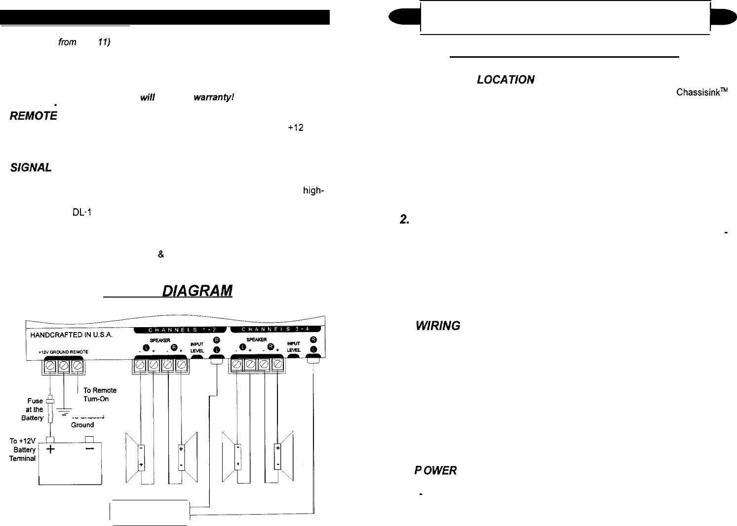
REMOT;
TURN-ON
Connect the “Remote” to the turn-on lead from the source unit. When
+12
volts
is received, the amplifier will turn on. Soundstream’s Remote200 20 gauge turn
on lead works perfectly.
SGNAL
CABLE
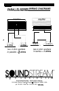
Depending on your application, you may use one, two, or three pairs of signal
cables to drive your amplifier. To guarantee optimum performance, use a high-
quality cable that will be easy to install and has minimal signal loss such as
Soundstream’s
DL.1
or SL.1.
SPEAKER CABLE
Use a high quality, flexible, multi-strand cable for best performance and
longevity. Soundstream Speaker120
&
160 (12 and 16 gauge) are ideal.
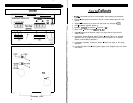
WIRING
DlAGRAM
-
To Chassis
I
HEAD UNIT
4
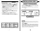
INSTALLATION STEP 4
t
I.
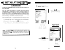
AMPLIFIER LOCATiON
The SA amplifiers employ highly efficient circuitry and a unique
ChassisinkW
design to maintain lower operating temperatures. Additional cooling may be
required if the amplifier is located in a tightly confined area, or when driving
especially low impedance loads at extremely high levels.
When mounting the amplifier, it should be securely mounted to either a panel in
the vehicle or an amp board or rack that is securely mounted to the vehicle. The
mounting location should be either in the passenger compartment or in the trunk
of the vehicle, away from moisture, stray or moving objects, and major electrical
components. To provide adequate ventilation, mount the amplifier so that there
are at least two inches of freely circulating air above and to the sides of it.
2.
3.
4.
SWITCHES
Set Input and Crossover switches to the appropriate positions (see pages 15
-
17).
MOUNTING THE AMPLIFIER
a. Using the amplifier as a template, mark the mounting surface.
b. Remove the amplifier and drill the holes.
c. Mount the amplifier to the surface using the provided hardware.
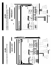
WIRlNG
a.
Run and connect the audio signal and remote turn-on cables to the amplifier
from the source unit.
b.
C.
d.
e.
f.
Carefully run the positive cable from the amplifier to a fuse or circuit
breaker within 18 inches of the battery.
Then connect the fuse or circuit breaker to the battery.
Leave the circuit
breaker off or the fuse out until everything is bolted down.
Secure the ground cable to a solid chassis ground on the vehicle. It may be
necessary to sand paint down to raw metal for a good connection.
Double check each and every connection!
Re-connect the fuse or circuit breaker.
5.
I=
OWER UP
INSTALLATION AND MOUNTING
Power up the system and look at the LED and it should be lit. There may be a
2
-
3 second delay from the time the source unit is turned on to the time the LED
on the amp turns on, which is normal. Once the amplifier power LED is on and
the source unit is playing, you should have sound coming from the speakers.
12
13