SA.164
I
-
/
I
i HANDCRAFTED IN U.S.A.
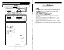
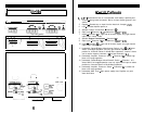
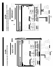
Top View (partial)
67 8
9 10
Side
View
.f-Y
i
/
/\
ii’
CHANNELS
1
&
2
LOW
PAS
m
FULL
RANGE
.14
15
\
MAIN FUSE
I-
i
11
Underside View
6
1.
2.
3.
4.
5.
6.
7.
6.
9.
10.
11.
12.
13.
14.
15.
v to
Callouts
+I
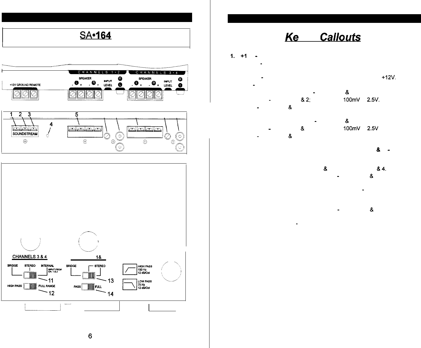
2V - Connected to fuse or circuit breaker, then battery’s positive post.
Ground
-
Main ground connection. Bolt to a clean chassis ground in the
vehicle.
Remote - Remote turn-on input from the head unit. Accepts
+12V.
LED
-
Indicates amplifier power on.
Speaker Output Connections
-
Channels 1
&
2
Input Level
-
Channels 1
812;
variable from
IOOmV
to
2.5’.
Inputs
-
Channels 1
&
2; right and lefl channel inputs; only right channel
input used in “Mono” mode.
Speaker Output Connections
-
Channels 3
&
4
Input Level
-
Channels 3
&
4; variable from
IOOmV
to
2.5V
Inputs
-
Channels 3
&
4; right and lefl channel inputs; only right channel
input used in “Mono” mode
[underside] Stereo/Bridged Mono/Internal Switch (ch 3 & 4) - Select
“Mono” for bridged operation (use only right channel input or stereo
position for 2-channel Stereo or Mixed Mono operation). “Internal” allows
you to use the inputs to channels 1
&
2 to feed channels 3
814.
[underside] Amplifier Crossover Switch
-
Channels 3
&
4; select high
pass or full range operation.
[underside] Stereo/Bridged Mono/Remote Switch - Channels 1 8 2;
select “Mono” for bridged operation (use only right channel input or stereo
position for 2-channel Stereo or Mixed Mono operation.
[underside] Amplifier Crossover Switch
-
Channels 1
&
2; select low
pass or full range operation.
[underside] Main Fuse
-
Main power supply fuse. Replace only with
same fuse value.


