


(
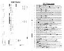
INSTALLATION STEP 3
)
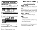
WIRING
POWER AND GROUND
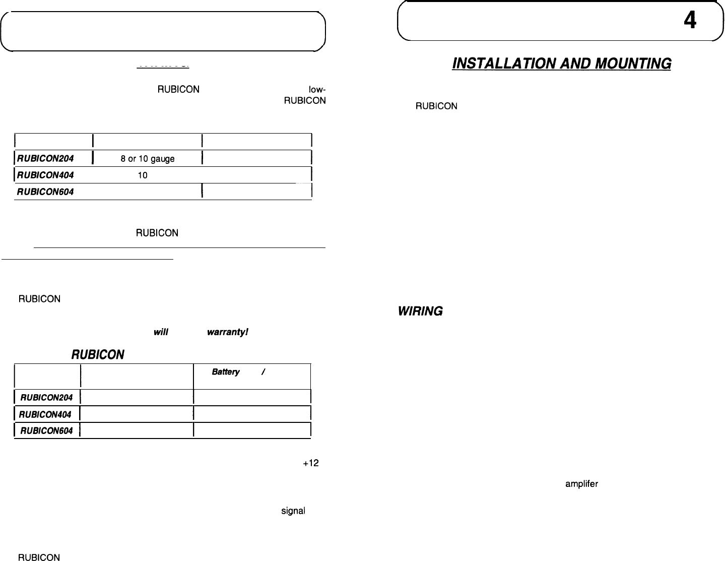
To ensure maximum output from your
RUBICON
amplifier, use high quality,
low-
loss power and ground cables and connections (4 gauge for 604). The
RUBICON
amplifiers will accept up to 8 gauge power and ground cables. Determine from
the chart below the minimum gauge power and ground wire for your application.
up to 10’
up to
20’
I
RUB/CON204
I
8orlOgauge
I
8 gauge only
I
I
RUBICON
I
8 or
IO
gauge
I
8 gauge only
I
I
RUBICON604
I
4 or 8 gauge
I
4 gauge only
-7
CIRCUIT BREAKERS AND FUSES
EXTERNAL
Like all audio components, the
RUBICON
amplifiers must be fused near the
battery. A fuse or circuit breaker must be located within 18” of the batterv. This will
prevent a fire in the event of a shorted cable. See the chart below to determine the
correct fuse value.
INTERNAL
The
RUBICON
amplifiers are fused with automotive-type fuses. In the event of
blown power supply fuses, replace with the correct value fuse found in the chart
below. Never replace the fuse with a higher value than what is supplied. This
may result in amplifier damage and
wi//
void the warranfy!
RUBICON
Amplifier Fuse Values
Amplifier Fuse
Battery Fuse
/
Circuit
Breaker
1
RUB/CON204
1
25 amp automotive 30 amp
1
RUl3iCOiv4o4
1
(2) 20 amp automotive
I
50
amp
I
1
RUB/CO/V604
1
(2) 30 amp automotive
I
80
amp
I
f
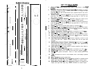
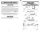
INSTALLATION STEP
4
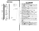
AMPLIFIER LOCATION
The
RUB/CON
amplifier employs highly efficient circuitry, a custom-engineered
heat sink, and a unique Chassisink construction to maintain lower operating
temperatures. Additional cooling may be required if the amplifier is located in a
tightly confined area or when driving especially low impedance loads at extremely
high levels.
When mounting the amplifier, it should be securely mounted to either a panel in
the vehicle or an amp board or rack that is securely mounted to the vehicle. The
mounting location should be either in the passenger compartment or in the trunk
of the vehicle, away from moisture, stray or moving objects, and major electrical
components. To provide adequate ventilation, mount the amplifier so that there
are at least two inches of freely circulating air above and to the sides of it.
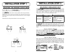
MOUNTING THE AMPLIFIER
a.
Using the amplifier as a template, mark the holes on the mounting surface.
b.
Remove the amplifier and drill the holes for the mounting screws.
C.
Secure the amplifier to the mounting surface using the supplied hardware.
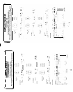
a.
b.
C.
d.
e.
f.
Run and connect the audio signal and remote turn-on cables to the
amplifier from the source unit.
Carefully run the positive cable from the amplifier to a fuse or circuit
breaker within 18” of the battery.
Connect the fuse or circuit breaker lead to the battery. Leave the circuit
breaker off or the fuse out until everything is bolted down.
Secure the ground cable to a solid chassis ground on the vehicle. It may
be necessary to sand paint down to raw metal for a good connection.
Double check each and every connection!
Re-connect the fuse or circuit breaker.
REMOTE TURN-ON
Connect the “Remote” line to the turn-on lead from the source unit. When
+I2
Volts is received, the amplifier will turn on.
SIGNAL CABLE
Use a high quality cable that will be easy to install and has minimal sianal loss
to guarantee optimum performance.
SPEAKER
The
RUBICON
amplifiers will accept up to
quality, flexible, multi-strand cable for best
16
CABLE
8 gauge speaker cable. Use a high
performance and longevity.
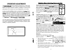
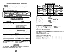
Power up the system and look at the Power LED; there may be a 2-3 second
POWER UP
delay from the time the source unit is turned on to the time that the LED on the
amp turns on, which is normal. Once the amplifer LED is on and the source unit
is playing, you should have sound coming from the speakers.
17