


(
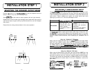
INSTALLATION STEP 1
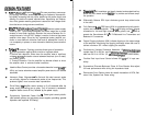
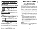
SELECTING THE SPEAKER OUTPUT MODE
Channels
1
through 4 of the
RUBICON204,
404 and 604 amplifiers have the
ability to operate in any one of the following modes:
Stereo
@TACT);
Use this mode for stereo operation (left and right channels).
Bridged Mono; Use this mode to get a bridged mono output while using only the
right channel input and gain control per pair of channels (for use with a singular
mono input.)
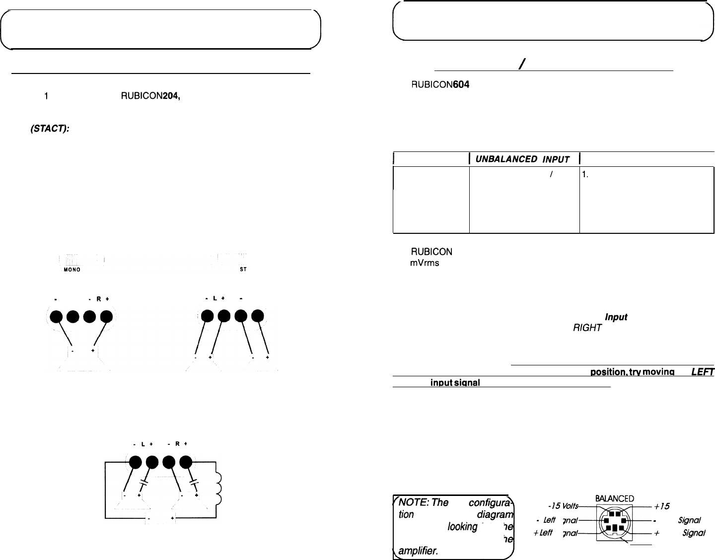
Please follow the wiring schemes below for the correct operation:
BRIDGED MONO
STEREO
-
L+
-R+
-
L+
-
R+
ST
MIXED MONO
-L+
-
R+
[
INSTALLATION STEP 2
BALANCED
/
UNBALANCED INPUT
The
RUBICON
amplifier has the ability to accept either a standard Unbal-
anced RCA signal input, or a Balanced “Pro Audio” style input signals with the use
of the Soundstream BLT Balanced Line Transmitter or some other balanced line
audio source.
Before installing your system, you should decide upon which
signal type you wish to run. There are advantages to both:
I
1
UNBALANCED
INPUT
1
BALANCED INPUT
I
1. Most preamplifier
/
1.
Improved Signal to Noise Ratio
source units have
(S/N Ratio).
ADVANTAGES
Unbalanced RCA outputs
2.
Excellent noise cancellation
(Industry Standard).
characteristics.
2. No Interface module is
3. Immune to noise radiated in
necessary.
the car audio environment.
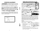
The
RUBICON
amplifiers’ signal inputs accept a wide range of input level: from
300
mVrms
to 5.0 Vrms for both Balanced and Unbalanced inputs. For the best
S/N Ratio, we recommend that the input level controls be set as far down as
possible (rotated counter-clockwise), while maintaining an acceptable level of
output.
Using the “Unbalanced” RCA Input
When using the Unbalanced RCA input, the RlGHT channel input signal switch
MUST be in the “UNBAL” position. Also, when first installing the amplifier using
this input configuration, we suggest that the left channel input signal switch be in
the “UNBAL” position as well.
If you
experience alternator
wine or other instal-
lation noise with both switches in the “UNBAL”
Dosition,
trv
movinq
the LEFT
channel
inout
sicanal
switch to the “BAL” position. This should remove any
system noise due to the installation.
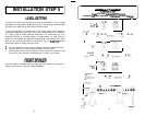
Using the “Balanced” RCA Input
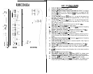
When using the Balanced 6-pin DIN audio input, both switches MUST be in the
“BAL” position. Also, we recommend that when using this input configuration, the
input level controls be set to the “minimum” position (rotated counter-clockwise).
The system gain should then be adjusted on the BLT Balanced Line Transmitter,
other other balanced line audio source. For the pin configuration, see the dia-
gram below:
(NOTE:
The
pin
tion
shown in the
is the view
looking
into th
Balanced input
jack on
th
LampMier.
EMLANCED
-
Lefl
Signal
-r5
v”3f!lL?E
+
left
Signal
+
15 Volts
-
Right Signa!
+
Right
Sl’gnol!
Shield
15
14